


p. 18
AVM Around Vehicle Monitoring System Installation Guide
inView 360 HD Installation Guide
© Safe Fleet | July 2020 | All rights reserved
Document Number: XE-SNB100-C00-INSTALLPM-R0A
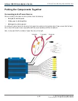
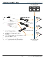
Connecting Antennas and an IR Receiver
1� Directly connect the GPS and Wi-Fi antennas to the ECU body�
2�
Connect the IR Receiver to the ECU harness’ IR receiver jack.
GPS Antenna
Wi-Fi Antenna
IR Sensor Receiver
Connecting to Vehicle Signals via the View Select Signal Cable Harness
If the ECU and the vehicle’s turn signals are connected to the ECU harness’ Left Right Reverse Trigger connector through
the View Select Signal Cable Harness, then the driver will receive with a left/right/rear view when the driver activates the
turn signals or places the vehicle in reverse�
Directly connect the signal cable harness to the ECU harness’
Left Right Reverse Trigger
connector�
View Select Signal
Cable Harness
Vehicle Right Signal
Vehicle Reverse
Signal
Vehicle Left Signal
Next Steps���
After you have successfully installed each of the system’s components, you’ll need to use the software to calibrate the
cameras� Please see the inView 360 HD AVM Calibration Guide for more about the calibration procedures�


