Frascold C-TSH Series Скачать руководство пользователя страница 8

8

FTEC11-01

4.

Lubrificazione

4.1

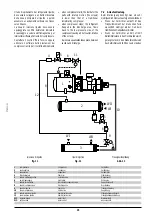
Il separatore integrato

Durante il funzionamento del compressore, il
flusso di refrigerante che fuoriesce dalla porta
di scarico trascina con sè una notevole quantità
di lubrificante che deve essere separato dal
refrigerante e convogliato nelle parti meccaniche
in movimento.
I compressori a vite serie C-TSH8 sono
equipaggiati con un separatore d’olio integrato
all’interno del quale l’olio si separa dal
refrigerante per gravità e attraversando il filtro
coalescente.
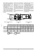
La figura 5 mostra una vista in sezione del
complesso separatore d’olio integrato/viti; nel
disegno si possono individuare gli elementi
essenziali del complesso che sono:

condotto di compressione (riferimento 1).
Attraverso il condotto, il refrigerante (e il
lubrificante trascinato) viene convogliato
dalla porta di scarico del carter viti nel
separatore d’olio integrato; all’uscita del
condotto, la repentina diminuzione di velocità
e di direzione del flusso provoca una prima
separazione del lubrificante  che si raccoglie
nella parte bassa del separatore.

filtro coalescente (riferimento 2).
Il suo attraversamento da parte del
refrigerante, provoca una ulteriore
separazione del lubrificante.

4.

Lubrication

4.1

Built-in oil separator

The screw compressor is characterised by a
lubrication system based on the injection of oil
into the parts in motion.
During functioning a huge quantity of lubricant
comes out from the screw compressor with a
pressure equal to the discharge one.
C-TSH8 series twin screw compressors are
equipped with a integral oil separator, where
inside lubricant is separated from the
refrigerant by gravity and impingement of the
oil demister.
Figure 5 shows the section view of the complete
oil separator/screws; from the drawing it is
possible to identify the basic elements of the
assemble, in details:

discharge duct (reference 1).
Through the duct the refrigerant (and the
discharged lubricant) is directed from the
discharge port of the screw housing into the
integral oil separator.
At the outlet of the discharge duct the rapid
reduction in speed and flow direction
gives the first lubricant separation with the
separated oil falling into the lower part of
the separator.

oil demister (reference 2).
The refrrigerant passing through the
demister gives an additional oil separation.

4.

Schmierung

4.1

Angeflanschten Ölabscheider

Der Schraubenverdichter ist charakterisiert durch
ein Schmiersystem auf der Basis von
Öleinspritzung.
Während des Betriebes gelangt eine große
Menge Schmiermittel aus dem Verdichter mit
dem gleichen Druck der Hochdruckseite.
Während des Betriebes strömt eine große
Schmiermittelmenge aus dem Verdichter aus, die
von der Kältemittel getrennt werden soll und in den
mechanischen Teile in Bewegung befördert.
Die C-TSH8 Schraubenverdichter sind komplett
mit einem angeflanschten Ölabscheider und auf
der Innenseite trennt das Öl sich vom Kältemittel
für Schwere, Zentrifuge und Durchqueren von
Ölabscheiderfilter.
Die Abb.5 zeigt den Satz angeflanschten
Ölabscheider/Schrauben; in der Zeichnung
siehen sich die folgenden Hauptteilen:

Druckleitung (Bezug 1).
Durch die Leitung, wird die Kältemittel (und
das geschleppte Schmiermittel) aus der
Drucktür der Schraubengehäuse in den
angeflanschten Ölabscheider befördert.
Bei Leitungsaustritt verursacht die
Verminderung der Fluß-geschwindigkeit und
-richtung eine erste Schmiermitteltrennung,
das in niedriges Seite des Ölabscheiders
sich sammelt.

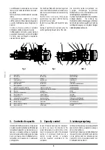
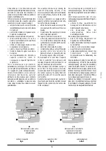
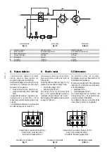
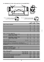
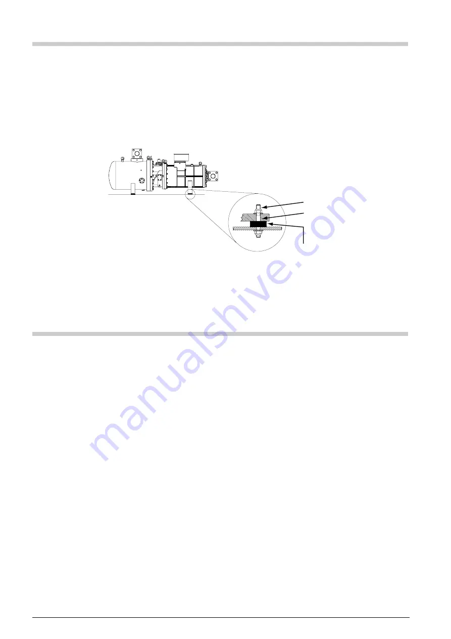
3. Fissaggio del compressore

È essenziale che il compressore venga fissato in
posizione orizzontale al fine di evitare anomale
sollecitazioni e, soprattutto, garantire la corretta
lubrificazione.
Il compressore può essere fissato direttamente
al telaio, oppure interponendo i molleggi
antivibranti forniti con il compressore (vedi
figura 4) e applicando ai dadi la corretta coppia
di serraggio pari a 30Nm.

fig. 4

fig. 4

Abb. 4

3. Compressor fixing

It is essential that the compressor is fixed to a
frame perfectly horizontal that, besides to
guarantee a working without anomalous stresses,
is indispensable for the perfect lubrication of parts
in motion.
The compressor can be direct mounted rigidly
on the frame or with vibration absorbers supplied
with the compressor (see figure 4) applying the
correct tightening torque of 30 Nm.

3. Aufstellung des Verdichters

Die Aufstellung des Verdichter muß waagerecht
erfolgen, um abweichende Beanspruchungen zu
vermeiden und die korrekte Schmierung zu
gewären.
Der Verdichter kann direkt am Rahmen
aufgestellt worden, oder mit
Schwingungsdämpfer geliefert mit den Verdichter
(siehe Abb.4) und indem an die Mutter die
richtige Drehmomente von 30 Nm befestigen.

M16
Ø 17 mm

Ø 50 mm
h = 20 mm

Содержание C-TSH Series

Страница 1: ...C TSH COMPRESSORICOMPATTIADOPPIAVITE COMPACTTWINSCREWCOMPRESSORS KOMPAKTDOPPELSCHRAUBENVERDICHTER Guida operativa Application guide Projektierungshandbuch 2003 11 01...

Страница 2: ...eavviso FRASCOLD SpA reserves the right to change at any time specifications or design without notice and without incurring obligations FRASCOLD SpA beh lt sich das Recht vor Spezifikationen oder Ausf...

Страница 3: ...pressor fixing 4 Lubrication 4 1 Built in oil separator 4 2 Oil cooling 5 The lubricant 5 1 Lubricant data 5 2 Recommendations 5 3 Lubricant mixing oil replacement 6 Compressor installation piping 6 1...

Страница 4: ...ainly due to exclusive design of screw profiles with a ratio 5 6 between male screw and female screw electrical motor with very high efficiency flowing through slots of the rotor suction gas is centri...

Страница 5: ...Saugventil 6 scatola terminali terminal box Elektrischer Anschlu kasten 7 filtro coalescente oil demister labscheiderfilter 8 pistone del controllo di capacit capacity control piston Leistungsregelun...

Страница 6: ...with no alignment problems The capacity control device consists of a three way solenoid valve directs the flow of oil in high pressure during its functioning cylinder directly connected with the sucti...

Страница 7: ...ndizioni solo la rimanente porzione delle viti quella compresa tra la luce di parzializzazione e la porta di scarico opera la compressione del refrigerante a ridotta capacit volumetrica corrisponde un...

Страница 8: ...nce 2 The refrrigerant passing through the demister gives an additional oil separation 4 Schmierung 4 1 Angeflanschten labscheider Der Schraubenverdichter ist charakterisiert durch ein Schmiersystem a...

Страница 9: ...ug 3 DieFormundAbmessungenverursacheneine pl tzliche Verminderung der K ltemittelflu geschwindigkeitundeineheftige nderung der Flu richtung AufderInnenseitesammeltsichdasgetrennte Schmiermittel w hren...

Страница 10: ...iermittel Das auf die Schrauben und die Lager eingespritzte Schmiermittel dient nicht nur zur Schmierung sondern dichtet die Schraubenprofile ab Esistsehrwichtigdas derSchmiermittelspezifische Eigensc...

Страница 11: ...der s uere und verseuchte l im Anlagen mit HCFC HFC K ltemittel F r weitere Vorschl ge steht die Technische Abteilung von FRASCOLD zur Verf gung linea di uscita dell evaporatore linea di uscita dell...

Страница 12: ...is principle with pump down system also to avoid the liquid refrigerant to flood the suction side of the compressor Dabei ist zu verhindern da fl ssiges K ltemittel w hrend der Stillstandsphase des Ve...

Страница 13: ...la presenza di eventuali residui solidi nel sistema frigorifero Per evitare eccessive concentrazioni di refrigerante nel lubrificante durante le fasi di arresto del compressore installare il riscaldat...

Страница 14: ...lation of a discharge pressure regulating valve is strongly recommended the valve has to be installed on the discharge line Under certain operative conditions it is possible to stop the compressor for...

Страница 15: ...ent aus folgenden Gr nden Wenn der Verdichter anl uft ist das Tr gheitsmoment der drehenden Teile wesentlich niedriger als der Hub beim traditionellen Hubkolbenverdichter Wenn der Verdichter anh lt st...

Страница 16: ...n suction and discharge The above allows screw compressor not to require an unloading start device 7 3 Economizer It is possible to increase the compressor efficiency by means an additional sucooling...

Страница 17: ...icklungsstart angetrieben Bei nderung die elektrische Motorverbindung siehe Abb 13 erhaltet sich zwei verschiedene Verdichtersanlauftypen Direktanlauf D O L Teilwicklungsanlauf P W S Der Teilwicklungs...

Страница 18: ...10 16 Seite 44 versehen Die Funktionen sind berwachung der maximalen Wicklungstemperatur 120 C durch sechs PTC Thermistoren die in den Statorswicklung eingeschaltet sind Dr cken MR f r die Handwieder...

Страница 19: ...3 Oil heater 10 4 Accessories 10 5 Water cooled oil cooler 10 6 Air cooled oil cooler 10 7 Oil strainer 10 8 Flow switch 10 9 Electronic module for flow switch 10 10 Solenoid valve 10 11 Oil sight gla...

Страница 20: ...maler Betriebstrom A LRA Corrente a rotore bloccato A corrente a rotore bloccato con collegamento D O L Locked rotor current A locked rotor current with connection D O L Anlaufstrom A Anlaufstrom mit...

Страница 21: ...compressore Compressor model Verdichtermodel 10 4 Accessori Accessories Zubeh r composto da filtro olio flussostato valvola elettromagnetica indicatore di passaggio modulo elettronico per flussostato...

Страница 22: ...eintemperatur 95 C temperatura uscita olio oil outlet temperature laustrittemperatur 70 C fattore di sporcamento fouling factor Verschmutzungsfaktor 0 Attacchi Connections Anschl sse 1 ingresso olio o...

Страница 23: ...ure laustrittstemperatur 70 C Dimensioni Dimensions Abmessungen A 50 5 mm 50 5 mm 50 5 mm B 42 5 mm 42 5 mm 52 5 mm C 619 mm 600 mm 600 mm OIL attacchi a saldare solder connections L tanschl sse 22 mm...

Страница 24: ...zione elettrica supply Elektroanschlu 220 230 V 50 60 Hz potenza assorbita input power Stromaufnahme 10 W grado di protezione safety class Schutzklasse IP65 attacchi a saldare solder connections L tan...

Страница 25: ...ce on nominal values 5 after 72 hours run in tc condensing temperature Die gezeigten Leistungswerte basieren auf den folgenden Bedingungen Sauggas berhitzung 10K Tolleranzbereich 5 dann 72 Stunden von...

Страница 26: ...onomizer senza economizzatore without economizer ohne Economizer con economizzatore with economizer mit Economizer con economizzatore with economizer mit Economizer con economizzatore with economizer...

Страница 27: ...uerbetrieb te Verdampfungstemperatur tc Verfl ssigungstemperatur tm S ttigungstemperatur entspreched der Zwischendruck I limiti di impiego sono stati calcolati alle seguenti condizioni senza economizz...

Страница 28: ...ilter Thermostatisches Expansionventil Druckregelventil Magnetventil Mischventil Temperaturregler Feststofffilter Schauglas Saugfilter separatore d olio oil separator labscheider compressore a vite sc...

Страница 29: ...g h Performance data shown are based on the following conditions without economizer suction gas overheating 10K without liquid subcooling with economizer suction gas overheating 10K liquid subcooling...

Страница 30: ...57 9 m 3521 8 3261 1 2787 8 2374 0 2012 9 1699 2 Qo 142010 130270 109220 91120 75600 Pe 45 65 44 82 43 21 41 80 40 99 IB 71 3 70 1 67 9 65 9 64 8 m 3492 7 3234 3 2765 1 2354 9 1996 8 Temperatura di ev...

Страница 31: ...4218 7 3556 1 2980 4 Qo 255400 234030 195690 162730 134490 Pe 86 16 83 91 79 62 75 81 73 13 IB 142 1 138 6 132 0 126 2 122 1 m 6281 6 5810 1 4954 2 4205 7 3552 2 Temperatura di evaporazione Evaporati...

Страница 32: ...61 1 2787 8 2374 0 2012 9 1699 2 Qo 173750 161410 138830 118880 101340 Pe 50 78 50 19 49 05 48 10 47 79 IB 78 6 77 8 76 0 74 6 74 2 m 3492 7 3234 3 2765 1 2354 9 1996 8 Temperatura di evaporazione Eva...

Страница 33: ...onomizer R407C 50Hz C TSH8 100 300 Y con economizzatore with economizer mit Economizer R407C 50Hz C TSH8 120 360 Y con economizzatore with economizer mit Economizer R407C 50Hz Qo 340220 291000 247720...

Страница 34: ...3 1782 9 Qo 151820 139620 117420 97970 81040 Pe 48 02 47 36 45 81 44 31 43 16 IB 74 5 73 6 71 5 69 4 67 8 m 3697 1 3421 8 2916 7 2468 4 2072 7 Temperatura di evaporazione Evaporating temperature Verd...

Страница 35: ...28 7 Qo 273340 251070 210560 175080 144190 Pe 90 81 88 70 84 26 80 17 76 98 IB 149 4 146 1 139 1 132 8 127 9 m 6656 2 6153 3 5230 3 4411 1 3687 8 Temperatura di evaporazione Evaporating temperature Ve...

Страница 36: ...2991 7 2537 3 2136 3 1782 9 Qo 177540 164850 141380 120330 101590 Pe 52 29 51 85 50 72 49 60 48 83 IB 80 9 80 3 78 5 76 9 75 7 m 3697 1 3421 8 2916 7 2468 4 2072 7 Temperatura di evaporazione Evapora...

Страница 37: ...341 7 4510 0 3775 9 3128 7 Qo 319640 296440 253520 215040 180760 Pe 99 15 97 24 93 20 89 51 86 78 IB 162 8 159 7 153 1 147 3 143 0 m 6656 2 6153 3 5230 3 4411 1 3687 8 Temperatura di evaporazione Evap...

Страница 38: ...1 2 Qo 92360 83480 67620 54060 42580 Pe 33 51 33 11 32 28 31 49 30 90 IB 53 0 52 3 50 8 49 4 48 4 m 2608 5 2385 9 1980 8 1625 3 1314 8 Temperatura di evaporazione Evaporating temperature Verdampfungst...

Страница 39: ...82 2 1650 8 Qo 168840 152630 123660 98920 77950 Pe 62 40 61 64 60 05 58 57 57 51 IB 103 7 102 5 100 0 97 7 96 1 m 4768 3 4362 1 3622 6 2973 8 2407 1 Temperatura di evaporazione Evaporating temperature...

Страница 40: ...7 2105 6 1742 4 1425 3 1149 6 911 2 Qo 115640 105950 88230 72610 58910 Pe 37 59 37 35 36 79 36 29 36 04 IB 59 2 58 8 58 0 57 3 56 9 m 2608 5 2385 9 1980 8 1625 3 1314 8 Temperatura di evaporazione Ev...

Страница 41: ...2 0 3154 8 2581 1 2082 2 1650 8 Qo 211390 193710 161360 132840 107850 Pe 69 78 69 36 68 42 67 59 67 25 IB 115 4 114 7 113 2 111 9 111 4 m 4768 3 4362 1 3622 6 2973 8 2407 1 Temperatura di evaporazione...

Страница 42: ...zer LP HP TS TR1 DR2 V2 V3 V1 TR2 V6 CH V5 TR2 TR1 DR2 TR2 TR1 L1 1 L1 2 L1 3 ECO CC ECO rispettare la sequenza di collegamento TR1 YXZ e TR2 WVU comply with the wiring sequence TR1 YXZ and TR2 WVU TR...

Страница 43: ...per avviamento PWS 1st PWS start contactor Erster PWS Sch tz TR2 2 teleruttore per avviamento PWS 2nd PWS start contactor Zweiter PWS Sch tz TS termostato di sicurezza safety thermostat Sicherheitsthe...

Страница 44: ...TSH8 30 120 Y C TSH8 40 120 Y C TSH8 40 150 Y C TSH8 50 150 Y C TSH8 50 186 Y C TSH8 60 186 Y C TSH8 60 210 Y C TSH8 70 210 Y DV 7 6 3 2 4 1 NP SV 7 1 SV 5 205 DV 661 368 17 1234 267 898 120 80 187 19...

Страница 45: ...hter C TSH8 30 120 Y C TSH8 40 120 Y C TSH8 40 150 Y C TSH8 50 150 Y C TSH8 50 186 Y C TSH8 60 186 Y C TSH8 60 210 Y C TSH8 70 210 Y 9 attacco iniezione di liquido economizzatore liquid injection econ...

Страница 46: ...DV mm mm 3 1 8 80 0 2 5 8 67 0 C TSH8 90 300 Y C TSH8 100 300 Y DV 7 6 4 2 3 1 SV 7 SV NP 5 17 DV 354 827 403 17 1584 140 60 240 230 470 1102 409 250 665 604 9 8 8 70 70 DV 7 6 4 2 3 1 SV 7 SV NP 5 1...

Страница 47: ...o di alta pressione high pressure connection Druckseiteanschlu 1 4 SAE 8 attacco di servizio service connection Betriebsanschlu 3 4 NPT 9 attacco iniezione di liquido economizzatore liquid injection e...

Страница 48: ......

Страница 49: ......

Страница 50: ......

Страница 51: ......

Страница 52: ...aldina MI ITALY phone 39 0331 7422 01 fax 39 0331 576102 http www frascold it e mail frascold frascold it Branches FRASCOLD Asia 10 Jalan Hikayat Singapore 769855 SINGAPORE phone 65 6851 7318 fax 65 6...

Отзывы: