

Parameter
Description
Fan & Pump - Recommended Settings
NOTE*: When entering parameters, any changes made will only be stored if the Enter button is pressed twice after making the change.*
0.00
Frequency command / Reference (Paramter that first appears when
VFD is powered up.)
Local Control: Set target speed (Hz) (*PID see below)
DRV
Drive Start / Stop Control Method (Looks like DRU on display)
Local Control: 0 (Keypad)
Remote Control: 1
FRQ
Frequency Setting Method (Looks like FR9 on display)
Local: 1 (Keypad-2)
PID Control: 0 (KeyPad-1)
Remote: 3 for 0-10V or 4 for
4-20mA
F1
Forward / Reverse Run Disable
Reverse Run Disable: 2
F24
High / Low Frequency Limit enable
If Needed: 1 (Do not use for PID control)
F26
Minimum frequency limit. (Only visibe if FU1-33 = Yes)
Set desired low limit (Hz) (Do not use for PID control)
F39
Output Voltage Adjustment (If motor rated voltage is less than input
voltage, set this parameter accordinglyy. For example, if Input Voltage is
480VAC & Motor Voltage is 460VAC, set parameter to 96%)
100%= Output voltage will be the same as input voltage when
drive is running at full speed.
F50
Electronic Motor Thermal Overload Protection
1 (Yes)
F59
Stall Prevention (Stall level can be adjusted if necessary on F60)
111*
H19
Input/Output Phase Loss Protection
11*- not needed for Single Phase input
H20
Power on Start (VFD will start if remote start contact is closed at drive
power-up)
1 (Yes)
H21
VFD will Restart After a Fault was Reset.
1 (Yes)
H22
Speed Search (VFD will start on the fly if motor is still spinning)
1110*
H26
Number of Auto Restart Attempts
3
H27
Restart Delay (Set as maximum as possible for your application)
60.0sec.
H30
Motor size: kW= HP x 0.75
Kilowatt rating of motor
H31
Number of Motor Poles = 7200/ max RPM of motor
Number of motor poles
H33
Motor Full Load Current = Full Load Amps x Service Factor
Motor Full Load Current
Additional Parameters for Proportional Integral Derivitive (PID) Control in Single Motor Applications
(Typically used when VFD needs to maintian a desired pressure or temperature based on direct sensor feedback to VFD)
H49
PID Control Enable
1 (Parameters “rEF” will not appear until this parrameter is set to 1)
*rEF
PID Set Point Reference Parameter
Set Point=(Desired press or temp) x 60Hz/ (Max Range of Sensor)
H50
Feedback for PID control: select 0 for 4-20mA or 1 for 0-10V
0 for 4-20mA feedback or 1 for 0-10V feedback
H51
Proportional Gain for PID Control Response
Higher percentage = greater speed change at same feedback
value
H52
Integral Time for PID Control Response
Higher number = longer response time at same feedback value
H56
Minimum Frequency Limit for PID Control
Set desired low limit in Hz
H61
Sleep Mode Delay Time
Desired sleep mode delay time in seconds
H62
Sleep Mode Frequency (VFD enters sleep mode when VFD speed
decreases below frequency entered here for time set on H-61)
Desired sleep frequency in Hz (If minimum frequency is entered
on H-56, set H-62 to .5-1Hz. higher than H-56)
H63
Sleep Mode Wake Up Level (Percentage of sensor range that feedback
signal must reach before VFD will wake up from sleep mode)
Desired level in % (for normal PID control, set level slightly lower
than desired press. Set opposite for inverted PID control)
Reset Parameters
H93
If Needed, Use this Parameter to Reset all Setting to Default
Reset all Setting: 1 (Will return to 0 when done).
NOTE:
For reversed PID control (VFD should increase speed when feedback value is more than a set-point) change I8 or I13 to 60Hz and I10
or I15 to 0.0Hz. To calculate a set-point =
60Hz-(Pset. x 60Hz/Pmax).
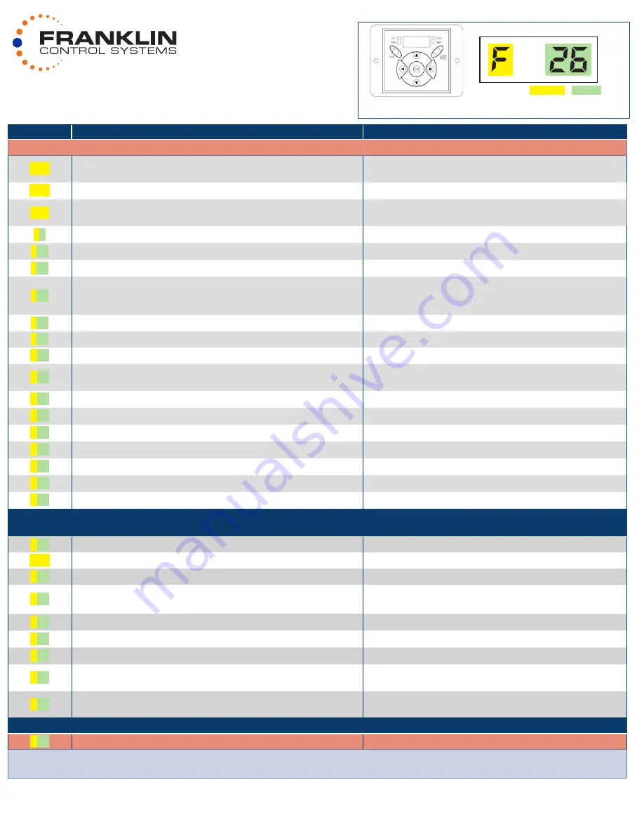
Using the LCD keypad display
PARAMETER “GROUP” “CODE”
Use the
t
(Left),
u
(Right) keys to scroll through the five parameter groups: DRV
u
F
u
H
u
u
DRV
Use the
p
(Up),
q
(Down) keys to scroll through parameter codes within each parameter group.
* For Binary Bit parameters the bit must be in the top position to equal On (1) and the bottom position to equal Off (0) and are numbered from right to left.
Example: H22: 1110 = ı ı ı ı = Bit 3 on, Bit 2 on, Bit 1 on, Bit 0 off)
** When entering parameters any changes made will only be stored if the Enter button is pressed twice after making the change.
GS/C Series VFD
QUICK START GUIDE


