19
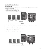
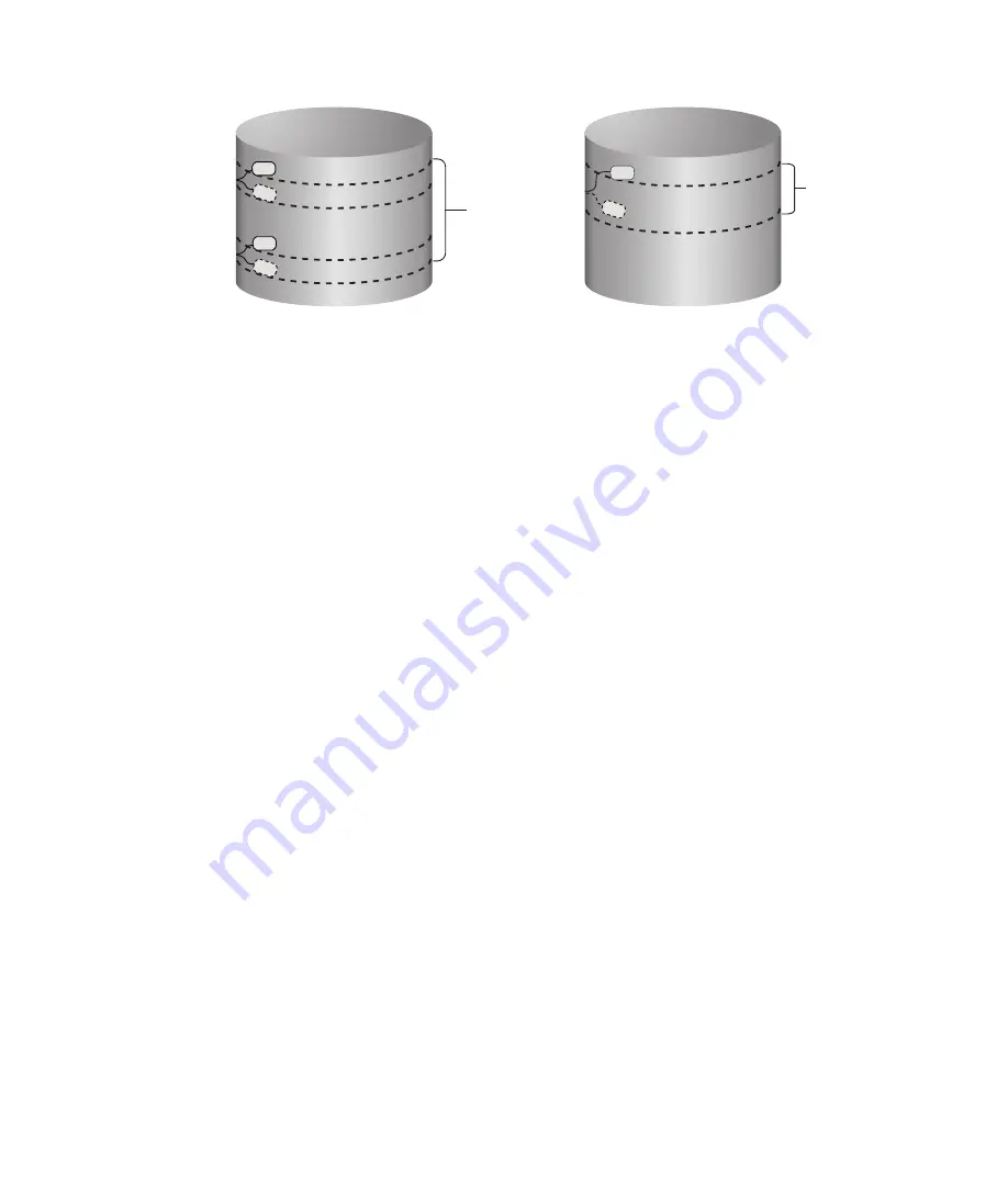
(OPEN)
(CLOSED)
(OPEN)
(CLOSED)
Two Control Switch Operation
Control
Switch-Run
Control
Switch-Stop
Pumping
Range
(OPEN)
(CLOSED)
One Control Switch Operation
Control
Switch-Run
Pumping
Range
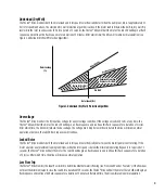
Figure 8: Control Switch Operations
NOTE:
All control switch configurations are superseded by the “FLOW SWITCH”. If the flow switch detects low flow it will “OPEN” and
override the run signals sent by the control switches to protect the motor and drive.
Start-Up and Operation
After all appropriate connections have been made, place the cover on the Fhoton™ Drive, then apply power to the controller. A steady
green light in the center of the cover indicates that the Fhoton™ Drive has DC power connected. No light can indicate that the polarity is
reversed, assuming sufficient DC voltage is available. Additionally, use a DC voltmeter to confirm proper polarity and sufficient DC voltage.
NOTE:
For optimal operation results, it is recommended to flush the bore well system until the water being discharged is clear and
free of debris. The flow switch should not be installed in-system during the flush. This will reduce the chances of the flow switch
being clogged by sediment and debris during initial start-up. (See Flow Switch section for details on bypassing flow switch to clear
debris on initial start-up).
Содержание Fhoton 2
Страница 1: ...Installation Guide FHOTON Drive ...
Страница 2: ...2 ...
Страница 29: ...Guía de instalación Dispositivo FHOTON ...
Страница 30: ...2 ...
Страница 57: ...Guide d installation FHOTON DRIVE ...
Страница 58: ...2 ...
Страница 85: ...Guia de instalação CONTROLADOR FHOTON ...
Страница 86: ...2 ...


