


NT 1963 E – 07/2020 _______________________________________________________________ 41
3.3.2.
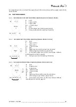
ELECTRIC THERMAL MODULE
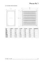
Size
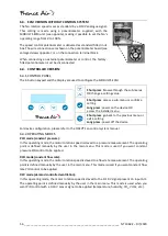
Power (kW)
I
max
per phase (A)
Power supply (V)
800
22.5
32.6
3-PH., 400 – 50 Hz
1500
22.5
32.6
3-PH., 400 – 50 Hz
4000
22.5
32.6
3-PH., 400 – 50 Hz
6000
48
69.6
3-PH., 400 – 50 Hz
8000
48
69.6
3-PH., 400 – 50 Hz
10000
72
104.3
3-PH., 400 – 50 Hz
12000
72
104.3
3-PH., 400 – 50 Hz
16000
90
130.4
3-PH., 400 – 50 Hz
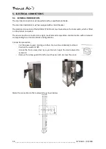
4.
INSTALLATION
4.1.
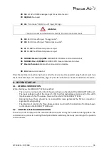
HANDLING AND MOUNTING THE PRODUCT
The unit must be installed so as to enable access for maintenance, service or removal operations. This
mainly means access to the removable panels, the electrical connections and to the panel equipped
with the fan unit.
4.2.
POSITIONING
The MODULYS® ECM module can be installed in every position, unless used with one or more ancillary
modules. In this case, the MODULYS® ECM module must be positioned horizontally.
WARNING
Under no circumstances must the maintenance panel be obstructed:
-
To enable the maintenance operations
-
To enable free access for setting the controller
-
To enable the fan motor assembly to cool down in case of fire
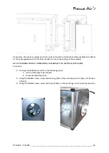
4.3.
AIR FLOW CONNECTIONS
Connect the MODULYS® ECM take-off directly onto the circular duct.
The connected ducts must have the same dimensions as the inlet and supply air take-off. A unit power
drop can be observed if ducts of smaller diameter are used, as well as in certain cases a reduction in
fan service life.
Connect the inlet and air supply take-offs (circular take-off) via flexible connectors (sleeves), to prevent
transmission of vibrations.
All ventilation duct connectors on the unit must be sealed with mastic or sealing tape.
The minimum distance between bends in the air ducts or adapters and the unit take-off is 3 times the
take-off diameter.
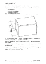
4.4.
RECTANGULAR DAMPER CONNECTIONS
The fresh air inlet will be closed when the machine is switched off. The damper installation
procedure is as follows:
•
Remove the panel with a Phillips screwdriver
•
Then unscrew the take-off throat via the inside
•
Refit the panel without the take-off throat
•
Fit the damper via 4 self-tapping screws


