24
ENGLISH
4. OPERATION INSTRUCTIONS
For the correct programming of the SAF-HD unit, proceed as follows:
1. Connect the SAF-HD unit to the electric network;
2. Connect the antenna cables to the relevant inputs;
3. Wait for the headend’s initialization (FRACARRO logo is displayed);
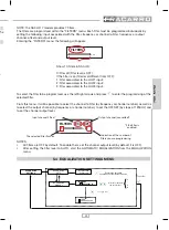
4. Enter the menu by pressing the
key and type in the user code (by default 1234); follow the pro-
gramming operations specifi ed within the following paragraphs (see PROGRAMMING INSTRUCTIONS
paragraph);
5. Make sure the output signal is available on the TV TEST output connector by using a signal measurer;
6. Connect the distribution cable to the TV output connector;
Alternatively to item 4, use a PC (with a KRS-RJ device and FHM software) to enter the headend program-
ming.
4.1 DEFAULT PROGRAMMING
Menu
Default parameters
Installer code
1234
Language
Italiano
Remote power
OFF
Filters status
OFF
B.III+DAB level (dB)
OFF
FM level (dB)
OFF
Final gain (dB)
15 (maximum)
Filters-inputs association
All the fi lters on UHF3
4.2 AUTOMATIC GAIN CONTROL FEATURES (AGC)
Every UHF selectable programmable module in the SAF-HD headend is equipped with an independent
circuit for gain control (AGC) to maintain a constant set output level if the input signal is within a determined
range.
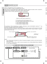
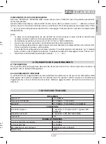
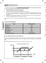
The following graph shows the performance of the automatic gain control circuit.
correct operating level range
Digital channel (OFDM): UHF
50
73
100
90
Output level
(dB
µV)
Input level
(dB
µV)
overload
AGC ON
AGC OFF
1
2
3
From the analysis of the above graphs, three fundamental cases can be distinguished:
1. Proper operation level.
If the terrestrial channel input is within the foreseen range, the AGC circuit works properly.
2. Low operation level.
This occurs when the input signal level on the selective programmable module is lower than the level
indicated in the technical specifi cations. The programming menu will display “LOW IN LEVEL” and the
module will return the output to a signal with a level that is proportionally lower than the maximum value
of the specifi cation.
3. Operation level under overload (or saturation).
This occurs when the input signal level on the selective programmable modules is higher than the level
indicated in the technical specifi cations. The module will return the output to a signal level that is propor-
tionally higher than the minimum value of the specifi cation.
4.3 WARNINGS FOR FILTERING AND CHANNEL CONVERSION
For the correct operation of the SAF-HD headend, the input signals should respect the following conditions:
1. Input signal level: 50 ÷ 73dBμV
The input level of the signals to fi lter must be between 50 and 73dBμV for CAG to work correctly.
2. Overall input power: 90 dBμV
This condition is met if all channels satisfy the previous item (level not higher than 73dB).
If the overall input power is more than 90dB, the input signal must be attenuated.
3. Max difference of the level among the fi ltered channels: 20dB
To avoid intermodulation, it is recommended that there is no fi ltering for channels that have a difference of
20dB between them. For the adjacent channels, we recommend not fi ltering channels that have a differ-
ence of more than 15 dB with the adjacent channel.
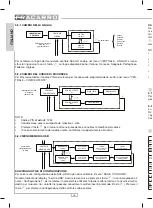
NOTE:
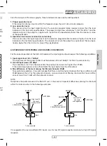
To optimize the performances of the SAF-HD unit, in the event of important differences among the channels
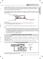
within the antenna, refer to the following examples:
FM
IN 1
IN 2
IN 3
SAF
SAF
ANT1200A
BLU420F
To the network
DE1-10
FM
IN 1
IN 2
IN 3
SAF
SAF
BLU220F
BLU920F
ANT1200A
Low level TV
channels management
High level TV
channels
management
Low level TV
channels
management
High level TV
channels management
To the network
It is suggested to use two different RF inputs: one for low RF signal reception and one for high RF signal
reception.

