20
ENGLISH
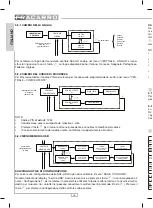
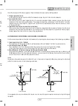
SAF-HD 10
SAF-HD 7
UHF2
BIII +
DAB +
FM
UHF3
UHF1
1
2
TEST TV
-25dB
Ingressi
Uscite
Inputs
Outputs
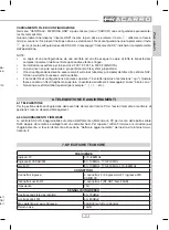
UHF1:
first programmable input of UHF band (470÷862 MHz);
UHF2:
second programmable input of UHF band (470÷862 MHz);
UHF3:
third programmable input of UHF band (470÷862 MHz);
BIII + DAB + FM: wide band input for III, DAB and FM band (87÷108 MHz, 170÷240 MHz and 470÷862 MHz);
TV:
output of TV signal in 87÷108 MHz, 170÷240 MHz and 470÷862 MHz band;
TV TEST: output test of TV signal with 25 dB attenuation;
(1):
Display (16 digits in 2 rows) and keyboard;
(2):
Grounding of the antenna installation (to be performed in accordance with EN60728-11);
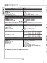
USB
RJ-45
LED di stato
LED
alimentazione
Connettore di
alimentazione
Power supply
LED
Status LED
Power supply
Connector
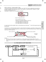
USB:
USB plug for pen drive connection and for copying/saving the headend unit configuration;
RJ45:
RJ45 jack for PC programmation and for firmware upgrade;
Power LED: ON (green) when the product is fed;
Status LED: shows that the headend unit is working;
ON: normal operation;
FLASHING: unit in boot or updating phase.
UHF3
UHF2
UHF1
LED to show remote power supply. When
the LED is ON (red), it means that the power
(12V) is activated for that input.
2.2 FLEXIBLE MATRIX OF FILTERS
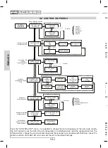
The filters can be associated with the 3 UHF1, UHF2 or UHF3 inputs by means of a flexible matrix. The as-
sociation of the filters to the UHF input that you desire is made during the programming phase either from
the keyboard or by the FHM programming software.
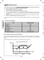
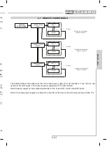
The matrix of SAF-HD 10 is defined as follows:
FILTRO
1
FILTRO
2
FILTRO
3
FILTRO
4
FILTRO
5
FILTRO
6
FILTRO
7
FILTRO
8
FILTRO
9
FILTRO
10
OUT RF
TEST RF
UHF 3
UHF 2
UHF 1
FM
B.III
DAB
B.III
DAB
FM
Fig. 2.1 - Division of filters in the SAF-HD 10 model
•
All selective filters can be associated to the UHF3 input;
•
The first 6 selective filters can be associated to the UHF2 input;
•
The first 3 selective filters can be associated to the UHF1 input;
•
The B.III/DAB/FM input is independent with separate regulations of the gains.
The 10 selective programmable filters can receive the signals from the 3 inputs in a completely flexible way.
All possible combinations can be set (for example, 1 channel from antenna 1, 3 from antenna 2 and 6 from
antenna 3, or 10 channels from the same antenna) by connecting the antenna with the highest number of
channels to be filtered to Input 3 and the antenna with the lowest number of channels to be filtered to Input 1.

