background image

VDC-7/VDC-15 Long Range Video/Data/RC Transmission System 

 User Manual

©

2020 FOXTECH All Rights Reserved


24

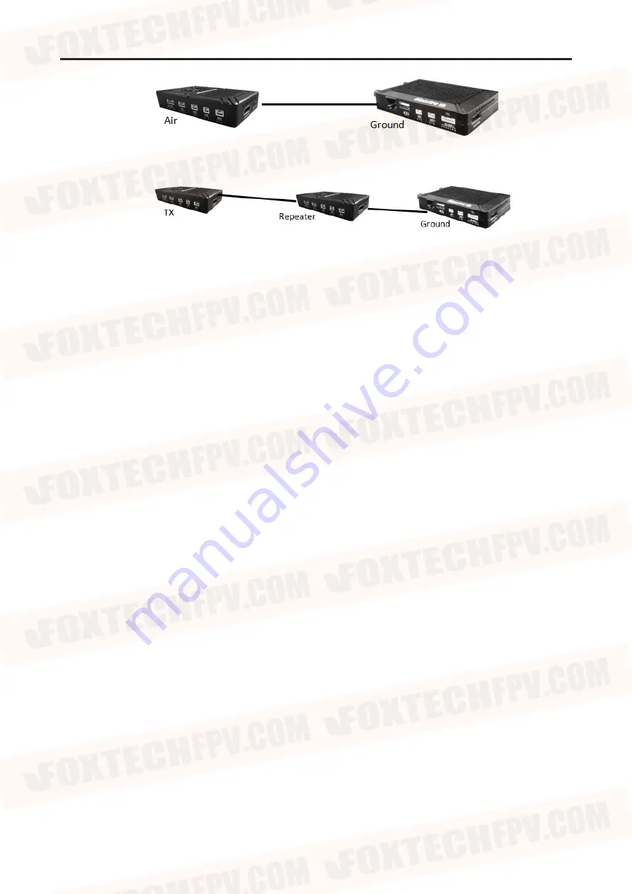
Point to Point

Repeater Mode

With Repeater mode, VDC-7/VDC-15 can be easily used under NLOS situation. You only need to buy one 
more air unit and then can establish a repeater system easily.

Содержание VDC-15

Страница 1: ...User Manual V2 0 VDC 7 VDC 15 Long Range Video Data RC Transmission System 2020 06...

Страница 2: ...Get Video Get data VDC 7 VDC 15 Instruction Quick Start VDC 7 VDC 15 with Mission Planner VDC 7 VDC 15 with VLC Improve RC Controller Distance Through SBUS Recording Video on Ground Unit Assistant In...

Страница 3: ...d all points completely Please strictly abide by the local radio frequency management regulations Please follow the installation steps in the manual to use this product Our company and agent will not...

Страница 4: ...t Air unit Ground unit Accessories 7Pin cable x2 For Power and UART1 Fiber glass antenna x2 For ground unit Air unit antenna extension cable For the connection for the air unit and the antenna Antenna...

Страница 5: ...he antenna should be installed downward and keep the antenna away from the metal on the drone 5 Make sure to use the matching antenna Before use 1 Make sure that all cables are connected correctly and...

Страница 6: ...one more air unit and simple configuration to achieve long distance transmission Please watch the instruction video for more information VDC 7 VDC 15 has an encryption function Users can Enable Disab...

Страница 7: ...source 2 Link indicator LED Pattern Description solid green Wireless link is established light off Wireless link is lost 3 Status Indicator LED Pattern Blink only in booting Description Blink 3 times...

Страница 8: ...3 4 7 G GND I O 5 T TXD from air unit to external O 6 R RXD from external to air unit I Number Character Description Input Output 1 T TX O 2 T TX O 3 R RX I 4 R RX I Number Character Description Input...

Страница 9: ...put interface 11 Button Press 10 seconds air unit will restore all parameters to factory setting 12 Mode switch WB is wide band using wide wireless frequency band NB is narrow band using narrow band t...

Страница 10: ...established light off Wireless link is lost 3 Status indicator LED Pattern Description Blink 3 times Initialization OK Frequency is 2 4G Blink 2 times Initialization OK Frequency is 1 4G Blink 1 time...

Страница 11: ...NB is narrow band using narrow band to multi modules transmission The air and ground unit should be the same direction 5 Ethernet port RJ45 Connecting to host computer Support RTSP TCP UDP protocol 6...

Страница 12: ...good connection Connect the camera gimbal to the air unit with HDMI SDI Ethernet cable And connect UART1 and SBUS to the flight controller Do not put the antenna near the motor or ESC otherwise the de...

Страница 13: ...along with the device to the ground unit They have common port SMA Make sure to tighten the joint The 2 fiber glass antenna should be 1 5m apart Connect the HDMI cable Connect the HDMI port with HDMI...

Страница 14: ...uter or ground station User can use third party software to decode such as VLC Mission Planner If you connect an IP camera to the air unit of VDC 7 VDC 15 the ground unit can also output FHD video to...

Страница 15: ...e FAQ It takes 15 seconds to start up After the system starts the wireless transmission can be established Video transmission will take 15 more seconds VDC 7 VDC 15 Instruction VDC 7 VDC 15 with Missi...

Страница 16: ...2 168 1 100 5 Get data There are three methods to get data from VDC 7 VDC 15 ground unit using Mission Planner UDP port via Ethernet TCP port via Ethernet UART COM Get data from UDP port Open Mission...

Страница 17: ...d TCP port number has been changed on the web page please fill in the new IP and port number For more information please go to the web page configuration Then click OK Mission Planner will get flight...

Страница 18: ...20 FOXTECH All Rights Reserved 18 6 Get video When you open the Mission Planner click Video and then Set GStream Source as show below Input the address rtspsrc location rtsp 192 168 1 36 stream0 laten...

Страница 19: ...ut the following address rtsp 192 168 1 36 554 stream0 Improve RC Controller Distance Through SBUS 1 Connect air unit SBUS to flight controller RC IN Using the SBUS cable in the accessory box to conne...

Страница 20: ...can use it to power the RC receiver Please pay more attention to the cable line order Recording Video on Ground Unit 1 Inserted the USB storage device into the USB port on the ground unit The HDMI out...

Страница 21: ...needed and click Set button to complete setup Click the Get button to get current frequency band 9 Select BW There are four BW to be selected 3MHz 5MHz 10MHz 20MHz Choose the BW you needed and click...

Страница 22: ...to get current working mode This function only needs to be set up on the VDC 7 VDC 15 air unit The ground unit can synchronize automatically If you select Repeater mode you need to select the air uni...

Страница 23: ...wer VDC 7 VDC 15 has three levels of power to choose In order to cause interference between devices please select the appropriate transmission power The specific RF power values are as follow 1 Low 15...

Страница 24: ...ion System User Manual 2020 FOXTECH All Rights Reserved 24 Point to Point Repeater Mode With Repeater mode VDC 7 VDC 15 can be easily used under NLOS situation You only need to buy one more air unit a...

Страница 25: ...he air unit default IP is 192 168 1 100 The ground is 192 168 1 36 In Repeater mode TX is 192 168 1 100 Repeater is 192 168 1 101 If you change the device to another IP address please access the web U...

Страница 26: ...the browser you will see the Welcome page Default username is admin password is 123456 Then you can login 2 Air setting In Air setting page user can change air IP Gateway and other parameter You can r...

Страница 27: ...e of UART1 and UART2 in Data setting page It will be in effect after rebooting User can change wireless parameter on Wireless Parameter setting page You can refer to the table below Web UI configurati...

Страница 28: ...le Click Send You will see the upgrade progress bar The system will restart when the upgrade is complete You can check the CODEC and FW version in this web page Additionally CODEC Version is for video...

Страница 29: ...anual 2020 FOXTECH All Rights Reserved 29 Reboot is used for system rebooting If user do not change the device IP address it will go to the Login page after rebooting If you change the IP address you...

Страница 30: ...DC 7 VDC 15 Ground Web UI 1 Login After you enter IP address 192 168 1 36 in the browser you will see the Welcome page Default username is admin password is 123456 Then you can login 2 Ground setting...

Страница 31: ...address in your browser after rebooting 3 Data setting User can change parameter of UART1 and UART2 in Data setting page UART1 supports two protocols Mavlink default and Transparent User can change pr...

Страница 32: ...tting page You can refer to the table below When you configure parameter through Web UI It will be in effect after rebooting 5 System Update Both ground and air unit are upgraded in the same way Pleas...

Страница 33: ...ideo bit rate Video delay Wireless Performance Power Range Power consumption Interface Video Performance 800MHz 1 4GHz 2 4GHz 800MHz 806MHz 825MHz 1 4GHz 1427MHz 1447MHz 2 4GHz 2408MHz 2480MHz 3MHz 5M...

Страница 34: ...rature Humidity Size weight Antenna air Antenna ground Environment Appearance MMCX Glue stick antenna Vertical 2 5dBi 2 0 SMA Fiber glass antenna Vertical 7dBi 2 0 40 70 40 85 5 95 non condensing Air...

Страница 35: ...the antenna and the RF cable 3 Please contact our company s after sales service HDMI monitor output OSD No Video Source Input 1 This OSD means the ground unit has established a connection with the ai...

Страница 36: ...nt is subject to change Download the latest version from https www foxtechfpv com vdc long range video data radio transmission system html For everyday updates please follow Foxtech Facebook page http...

Отзывы: