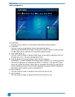
BIOS SETUP
28
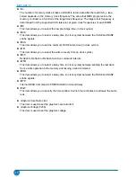
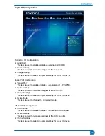
► tCL
The number of memory clocks it takes a DRAM to return data after the read CAS_L isas-
serted depends on the memory clock frequency. The value that BIOS programs into the
memory controller is a function of the target clock frequency. The target clock frequency is
determined from the supported CAS latencies at given clock frequencies of each DIMM.
► tRP
This item allows you to select the row precharge time (in clock cycles).
► tRCD
This item allows you to select a delay time (in clock cycles) between the CAS# and RAS#
strobe signals.
► tRAS
This item allows you to set the minimum RAS# active time (in clock cycles).
► tWR
This item allows you to select the write recovery time (in clock cycles).
► tRFC
Refresh to Refresh or Refresh to Active command interval.
► tWTR
This item allows you to select a delay time (in clock cycles) between sending the last data
from a write operation to the memory and issuing a read command.
► tRRD
This item allows you to select a delay time (in clock cycles) between the RAS# and RAS#
strobe signals.
► tRTP
Internal READ Command to PRECHARGE Command delay
► tFAW
This item allows you to specify the time window in which four activates are allowed the same
rank.
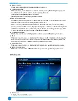
► Graphics Core Ratio Limit
This item is used to set the graphics care ratio limit.
► Graphics Voltage(1/256)
This item is used to set the graphics voltage.
Содержание H61AP Series
Страница 1: ...H61AP Series Motherboard User s Manual ...

