


Chapter 2 Installation Instructions
19
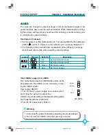
Wake-Up On Internal Modem (optional): WOM
Through this function, the system which is in suspend
or soft-off status can be waken up by a ring signal re-
ceived from the internal modem. When this function is
enabled, make sure an internal modem card which
supports this function is used. Connect the header to
the relevant connector on the modem card, set “Power
On by Ring” as “Enabled” in the “Power Management
Setup” of the CMOS Setup Utility. Save and exit, then
boot the operating system once to make sure this func-
tion takes effect.
+5V _SB
GND
WOM
1
Modem wake up
S-ATA Connectors (optional): SATA_1, SATA_2, SATA_3, SATA_4
The S-ATA connector is used to connect the S-ATA de-
vice to the motherboard. These connectors support the
thin Serial ATA cables for primary internal storage
devices. The current Serial ATA interface allows up to
150MB/s data transfer rate.
SATA _1/SATA _2/
SATA _3/SATA _4
GND
GND
GND
T X +
TX-
RX+
RX-
1
1394 Connector (optional): F_1394
The 1394 expansion cable can be connected to either
the front (provided that the front panel of your chassis
is equipped with the appropriate interface) or rear
panel of the chassis.
IrDA Connector: IR
This connector supports wireless transmitting and re-
ceiving device. Before using this function, configure the
settings of IR Mode from the “Integrated Peripherals”
section of the CMOS Setup.
+12V
GND
TPB -
TPA -
F_1394
1
2
9
10
+12V
TPB +
GND
Empty
TPA +
1
IR
+5V
GND
IRRX
IRTX
Empty
915PL7AE-Manual-EN-V1.0-01-25-04.p65
2005-5-26, 17:35
19