background image

8

WORKING WITH MICROLOG

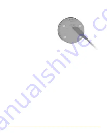
Disconnect the communication
cable from MicroLog and insert
the sensor connector cable in its
place (fig. 6). Connect the sensor
directly to the reed relay or to
the switch you are monitoring.
The sensor’s two terminals have
no polarity. Make sure that the
switch is not powered by a
voltage source; our sensor has
an internal pull-up resistor and therefore does not require any
voltage source.

MicroLog samples the sensor at the chosen rate; therefore switch
changes that are faster than the MicroLog sampling rate will not
be recorded. For example, if the MicroLog sampling rate is “every
1 minute” the switch being monitored should be open or closed
for at least 1 minute at a time in order for MicroLog to record
the changes.

When downloading the data to the MicroLog software, the data
will be displayed in two values representing the sensor’s “open”
and “close” states. There is no need to select the external sensor
before downloading the data.

fig. 6

Содержание MicroLog DT141

Страница 1: ...External Sensor CONTACT DT141 ACCESSORIES Range Connectors Internal pull up resistor open close screw terminals no need for external power source User Guide for MicroLog EC600 and EC650...

Страница 2: ...s one of MicroLog s 6 external sensors Using this sensor you will be able to monitor reed relays and door switches allowing you to correlate between temperature changes and door status This sensor can...

Страница 3: ...le with MicroLab software versions 2 0 or higher Follow the steps below to select the sensor using MicroLab 3 0 or higher versions Selecting the MicroLog External Sensor 1 Connect MicroLog to the PC u...

Страница 4: ...4 fig 2...

Страница 5: ...alues Open and Close You may select your own values by replacing the default open close from the DEFINE NEW SENSOR menu In the DEFINE NEW SENSOR dialog box select ADD and select CONTACT Then fill in t...

Страница 6: ...communication cable 3 Click on STOP in the left hand toolbar 4 Activate the MicroLog external sensor by clicking on the Sensor Selection button next to the external sensor on the right hand toolbar fi...

Страница 7: ...fig 5 3 The dialog box should close automatically If the box is not closed it means that MicroLog is either not connected to the PC or is in Sleep mode Before disconnecting the communication cable an...

Страница 8: ...not require any voltage source MicroLog samples the sensor at the chosen rate therefore switch changes that are faster than the MicroLog sampling rate will not be recorded For example if the MicroLog...

Страница 9: ...warranty products will be repaired on a charge basis Return of items Authorization must be obtained from your FOURIER SYSTEMS distributor before returning items for any reason When applying for autho...

Страница 10: ...EXTERNAL SENSORS Temperature Sensor 50 to 100 C 58 to 212 F PH Sensor 1 14 pH Voltage Sensor 0 10 V Current Sensor 0 20 mA Light Sensor 0 5000 lux Contact Us For further information please contact ou...

Отзывы: