background image

vice Guide


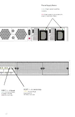
PORT 1 – 4 Link/Activity 

Amber

: Transmi

ng & 

Receiving data. 

O

: Port is not in use.  


PORT 1 – 4 Speed 


O

: Port is not in use.


17 

Power Supply Status


Green

Power supply is opera�ng

normally.


Red: 

Power supply is not connected to 

power or mechanical failure.


Green

: Port is connected

at 1Gbps or 10Gbps.

Содержание FortiTester 2000E

Страница 1: ...FortiTester 2000E QuickStart Guide ...

Страница 2: ...t Fortinet enters a binding written contract signed by Fortinet s General Counsel with a purchaser that expressly warrants that the identified product will perform according to certain expressly identified performance metrics and in such event only the specific performance metrics expressly identified in such binding written contract shall be binding on Fortinet For absolute clarity any such warra...

Страница 3: ......
Страница 4: ... La reistrazione ti permette di usufruire di Supporto Tecnico Nuove funzionalita Proteezione dalle ultime minaccce Debe registrar el producto para recibir Apoyo técnico Nuevas funcionalidades del producto Protección contra ataques https support fortinet com Toll free 1 866 648 4638 Phone 1 408 486 7899 Fax 1 408 235 7737 Email register fortinet com 登録のお願い 本日 フォーティネッ ト製品の登録をしてくだ さい 登録すると次のメリッ トがありま...

Страница 5: ...er 2000E Quickstart Guide 2 Power cables Ethernet cable Console cable 5 Rubber feet 6 M4 screws for sliding rails handles 2 M6 rack mount screws 2 Sliding rail handles 2 Sliding rails FortiTester 2000E QuickStart Guide 2 Sliding rails ...

Страница 6: ...FortiTester unit into a rack 1 Ensure that the FortiTester unit is placed on a stable surface prior to rack mount installation 2 Assemble the rails and install the system in the rack following the safety instructions and the rack installation instructions in Rail Installation p 6 3 Verify that the spacing around the FortiTester unit conforms to requirements and that the unit is level 4 Connect the...

Страница 7: ... pull the chassis inner member out 2 Use the standoffs to mount the chassis inner member to the chassis 3 To attach the cabinet outer member of the rail first ensure that the safety lock is in the unlocked position Then insert the stag into the upper and lower square holes on the EIA rail from the back of the rail Finally push the safety lock forward to secure the bracket Press trigger down to rele...

Страница 8: ...rt the chassis inner member into the cabinet member When you push the chassis back into the cabinet press the trigger down to release the slide from the locked position Release safety lock before mounting Push the safety lock forward to secure Retainer is in fully open position Press trigger down to unlock slides 8 ...

Страница 9: ...ch time that you are inserting a transceiver Caution Transceivers are static sensitive devices Use an ESD wrist strap or similar grounding device when handling transceivers Do not install or remove transceivers while fiber optic cables are still attached This can cause damage to the cables cable connectors and the optical interfaces It may also prevent the transceiver from latching correctly into ...

Страница 10: ...cable from the transceiver connector and install a clean dust plug in the transceiver s optical bores 3 Pull the extraction lever out and down to eject the transceiver If you are unable to use your finger to open the lever use a small flat head screwdriver or other similar tool to open the lever 4 Hold the sides of the transceiver and carefully pull it away from the cage socket 5 Replace the cap o...

Страница 11: ...ce and then into a grounded electrical outlet or a separate power source such as an uninterruptible power supply UPS or a power distribution unit PDU If the appliance has a redundant power supply connect each power cable to a different power source 3 Setup Options A Web Browser B Terminal Emulation ...

Страница 12: ...nt port default subnet For example from the Windows 7 Control Panel go to Network and Sharing Center Click the Local Area Connection link and then click the Properties button Select Internet Protocol Version 4 TCP IPv4 and then click its Properties button Select Use the following IP address and then enter the following settings IP address 192 168 1 2 Netmask 255 255 255 0 3 To connect to the web U...

Страница 13: ...e management computer select the COM port and use the following settings Baud Rate 9600 Data bits 8 Parity None Stop bits 1 Flow Control None 3 Press Enter on your keyboard to connect to the CLI 4 Login using username admin and no password You can now proceed with configuring your device Get started by typing for a list of available commands Begin typing a command then type for a list of available...

Страница 14: ... for system management Console Optional connection to the management computer Provides access to the CLI Grounding Screws Provides extra grounding 14 FortiTester 2000E Reset Button Reboots the system Console Optional connection to the management computer Provides access to the CLI ...

Страница 15: ...your DUT Power Switch To turn the power ON OFF Power Supply Warning Buzz Reset Button To disable the power supply warning buzz Power Connections 100 240V AC 50 60 Hz 5 3 A Redundant Power Supply 15 2 3 4 SPF Ports 1 4 10 Gigabit Ethernet ports for connections to your DUT ...

Страница 16: ... system alarm Red System failure HDD Flashing Amber HDD in use MGMT Port Link Activity Flashing Amber Transmitting Receiving data Off No link established MGMT Port Speed Amber Port is connected at 1Gbps Green Port is connected at 100Mbps Off Port is connected at 10Mbps or is not in use 16 ...

Страница 17: ... ng Receiving data Off Port is not in use PORT 1 4 Speed Off Port is not in use 17 Power Supply Status Green Power supply is opera ng normally Red Power supply is not connected to power or mechanical failure Green Port is connected at 1Gbps or 10Gbps ...

Страница 18: ...plate ratings should be used when addressing this concern Surtension Il convient de prendre l ensemble des précautions nécessaires lors du branchement de l équipement au circuit d alimentation et être particulièrement attentif aux effets de la suralimentation sur le dispositif assurant une protection contre les courts circuits et le câblage Ainsi il est recommandé de tenir compte du numéro d ident...

Страница 19: ...uthority to operate the equipment Industry Canada Equipment Standard for Digital Equipment ICES Canada CAN ICES 3 A NMB 3 A This digital apparatus does not exceed the Class A limits for radio noise emissions from digital apparatus set out in the Radio Interference Regulations of the Canadian Department of Communications Cet appareil numérique n émet pas de bruits radioélectriques dépassant les lim...

Страница 20: ...chedules and location of training programs in your area http www fortinet com support training html Technical Discussion Forums Communicate with other customers and Fortinet partners about Fortinet products services and configuration issues https support fortinet com forum FortiGuard Threat Research and Response Up to date information on vulnerabilities and threats includes a virus scanner IP sign...

Отзывы: