fortessa FTDEV1 Series Скачать руководство пользователя страница 14

-11-

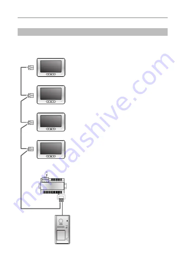
 Basic IN-OUT  Wiring in Standard Mode

Connecting Multiple Monitors

WIRING

• 

Other monitors are available.

• 

Please set door station into group calling 
mode if there are more than 4 monitors 

operated with one push button, or apart

-

ment.(Refer to Page 8)

• 

Distributor is unnecessary in full audio 

system,  and  IN-OUT  mode  is  recom

-

mended.

• 

For the last monitor connected to the 

system, DIP6 should set to 

ON

ID=0

Code=1, DIP6=off

(Master)

Code=1, DIP6=off

(Slave 2)

Code=1, DIP6=on

(Slave 3)

BUS(IM) BUS(DS)

FTDEV1PSU8

AC~

230VAC

Code=1, DIP6=off

(Slave 1)

Содержание FTDEV1 Series

Страница 1: ...USER MANUAL Please read this manual carefully to ensure safe and correct operation Keep this manual well for future reference FTDEV1 FTDEV2P FTDEV1 Series 2 WIRE SYSTEM ...

Страница 2: ......

Страница 3: ...Station Calling Mode 4 Setting Unlock Mode 6 Setting Unlock Time 6 Setting Nameplate Illumination Mode 7 Setting Night View LED Illumination Mode 7 Setting Ring back Tone 8 WIRING 9 Connecting Electric Lock 9 Connecting Basic One to one 10 Connecting Multi Door Stations 10 Connecting Multi Monitors 11 APPENDIX 13 Precautions 13 Specification 13 Cables and Requirments 14 ...

Страница 4: ... ACDB_MLEADER_CLASS Rainy cover Rainy cover The distance between the top of main unit and rain cover should be not less than 3mm Main unit Main unit 3mm 1 Connect the cable correctly 2 Use the appropiate fixing then attach the rain shield and main unit to the wall the distance between the top of main unit and rain cover should be not less than 3mm 3 Install the name plate 4 Attach the front panel ...

Страница 5: ...onnect if the door panel is powering the lock directly DO NOT use if a remote PSU is powering the lock 1 2 3 Lock Control Jumper PIR Motion Detector Terminal compatible monitor required 12V GND PIR L1 L2 PL S S Terminal Connections External Motion Detection Note The supplied monitor FTDEVM43 in the kit does not support motion detection function The door station is equipped with a terminal to conne...

Страница 6: ...r on the unit and by the sound of the buzzer Order Setting items Setting range Default value 1 Setting door station address 0 3 0 2 Setting door station calling mode Standard Group calling mode Standard calling mode 3 Setting the unlock mode 0 opened 1 closed 0 opened 4 Setting the unlock time 01 to 99 seconds 1 seconds 5 Setting the nameplate illumination mode On Off Auto On 6 Setting night view ...

Страница 7: ...ton to set the fourth door station UNLOCK Indicator OFF TALK Indicator OFF Buzzer Beep Beep UNLOCK Indicator OFF TALK Indicator OFF Buzzer Beep Beep Beep UNLOCK Indicator OFF TALK Indicator OFF Buzzer Beep Beep Beep Beep ID 0 1st door station ID 1 2nd door station ID 2 3rd door station ID 3 4th door station SETUP INSTRUCTIONS During Setting Mode you can change the address of door station by pressi...

Страница 8: ...tor with address 01 by default Call buttonB call the monitor with address 02 by default Call buttonA Call all monitors in group address from 00 15 one of the monitor should be set to 00 Call buttonB Call all monitors in group address from 16 31 one of the monitor should be set to 16 UNLOCK Indicator OFF TALK Indicator ON Buzzer Beep Beep In standby mode press KEY_SET button twice UNLOCK Indicator ...

Страница 9: ...E indicator will continue to blink while in Setting mode The Setting Mode will exit 10 seconds after the last button has been pressed To exit Setting Mode press KEY_SET button twice Setting Unlock Time By default the unlock time is 1s this can be altered from 1s 99s Follow the steps UNLOCK Indicator ON TALK Indicator OFF Buzzer Beep Beep In standby mode press KEY_SET button three times UNLOCK Indi...

Страница 10: ...ting mode The Setting Mode will exit 10 seconds after the last button has been pressed To exit Setting Mode press KEY_SET button twice Setting Night View LED Illumination Mode There are 3 working modes for night view LED indicator Normally on Normally off and Auto Auto is default to change the setting UNLOCK Indicator ON TALK Indicator OFF Buzzer Beep Beep In standby mode press KEY_SET button thre...

Страница 11: ...r ON Buzzer Beep Press KEY_1 button to set the ring back call tone ringing one time UNLOCK Indicator ON TALK Indicator ON Buzzer Beep Beep Press KEY_1 button again to set the ring back call tone ringing continuously UNLOCK Indicator ON TALK Indicator ON Buzzer Beep Beep Beep Press KEY_1 button again and again to close ring back call tone Press KEY_1 If setting mode has not been exited you can chan...

Страница 12: ... is not timed 5 The Unlock Mode must be set to 0 by default 1 An external power supply must be used 2 The relay contact are restricted to 24Vdc 1A 3 The jumper must be taken off before connecting and applying power 4 Setup the Unlock Mode according to different lock types Power on to unlock type Failse cure Unlock Mode 0 by default Power off to unlock type Fail safe Unlock Mode 1 EB LOCK Jumper po...

Страница 13: ...C FTDEV1VD A B C D OFF ON Impedance switch BUS IM BUS DS FTDEV1PSU8 AC ID 0 1st door station ID 1 2nd door station ID 2 3rd door station ID 3 4th door station L1 L2 PL S S L1 L2 PL S S L1 L2 PL S S L1 L2 PL S S To monitors The door station work in Standard mode in this situation Refer to Page 8 in detail The door station is also compatible with other monitors which are available If additional moni...

Страница 14: ...are more than 4 monitors operated with one push button or apart ment Refer to Page 8 Distributor is unnecessary in full audio system and IN OUT mode is recom mended For the last monitor connected to the system DIP6 should set to ON ID 0 Code 1 DIP6 off Master Code 1 DIP6 off Slave 2 Code 1 DIP6 on Slave 3 BUS IM BUS DS FTDEV1PSU8 AC 230VAC Code 1 DIP6 off Slave 1 ...

Страница 15: ... instructions for more details WIRING FTDEV1VD A B C D OFF ON Impedance switch BUS IM BUS DS Code 1 DIP6 on Code 2 DIP6 on Code 3 DIP6 on Code 4 DIP6 on ID 0 FTDEV1PSU8 AC 230VAC Star Topology Wiring With FTDEV1VD in Standard Mode ...

Страница 16: ...cian who is familiar with the ap propriate standards and technical requirements of the product taking in to consideration the latest building regulations Disconnect power before installing or servicing Never modify the unit there are no user serviceable parts inside APPENDIX Power supply DC 24V Power consumption Standby 0 8W Working 3W Camera lens Color CMOS 520TVL 1 4 camera 1050 wide angle Lock ...

Страница 17: ...ed in the system Using different cables may also affect the maximum distance which the system can reach Cable and distance unit m IM Indoor Monitor Cable Usage A B 2 IM B 16 IM Twisted cable 2x0 75mm2 60 100 40 Twisted cable 2x1mm2 80 120 60 A B FTDEV1PSU8 Basic IN OUT Wiring Mode ...

Страница 18: ... 15 B A C 2 2 FTDEV1VD FTDEV1PSU8 Cable and distance unit m Cable Usage A B C Twisted cable 2x0 75mm2 60 60 30 Twisted cable 2x1mm2 80 80 40 APPENDIX Star Topology Wiring Mode With FTDEV1VD ...

Страница 19: ... 16 Note ...

Страница 20: ...we reserve the right to change specification with out prior notice Errors and omissions excepted These instructions have been carefully checked prior to pub lication However no responsibility can be accepted by Challenger Security Products for any misinterpretation of these instructions Distributed by CHALLENGER SECURITY PRODUCTS 10 Sandersons Way Blackpool FY4 4NB enquiries challenger co uk www c...

Отзывы: