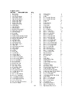
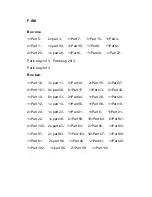
Force F-SM Скачать руководство пользователя страница 25

F-SM 


Box one


1×Part 5

   2x part 3

  1×Part 7

  1×Part 15

 1×Part 4


2×Part 1

   1x part 94

 1×Part 95

 1×Part 9

  1×Part 2


2×Part 25

  1x part 28

 1×Part 6

  1×Part 29

 1×Part 27


Parts bag 1of 3

Parts bag 2of 3


Parts bag 3of 3


Box two


1×Part 16

  1x part 11

 2×Part 34

  2×Part 35

 2×Part 37


2×Part 101

  9x part 36

 6×Part 17

  1×Part 13

 2×Part 33


1×Part 10

  8x part 43

 2×Part 44


1×Part 26

 1×Part 24


1×Part 12

  1x part 14

 1×Part 96

  1×Part 98

 1×Part 18


2×Part 20

  1x part 23

 1×Part 31

  1×Part 8

  1×Part 21

1×Part 22

   1x part 38

  2×Part 59

  10×Part 60

  5×Part 61


2×Part 100

 2x part 63

 1×Part 64

  2×Part 92

  1×Part 93


1×Part 97

   2x part 63

  7×Part 103

 10×Part 57

  1×Part 89


1×Part 91

   2x part 90

  1×Part 40

  1×Part 41

  1×Part 42


1×Part 102

  1x part 88

  2×Part 99

  1×Part 110


Содержание F-SM

Страница 1: ...instructions carefully before using this product Table of Contents Safety Notice Hardware Identifier Assembly Instruction Parts List Model F SM Retain This Manual for Reference 11 09 23 OWNER S MANUA...

Страница 2: ...MACHINE HARDWARE PACK 4 SMITH MACHINE ASSEMBLY INSTRUCTIONS 6 EXPLODED DIAGRAM 21 SMITH MACHINE PARTS LIST 22 WEIGHT RESISTANCE CHART 23 BEFORE YOU BEGIN Thank you for selecting the F SM For your saf...

Страница 3: ...or its intended use as described in this manual DO NOT use attachments not recommended by the manufacturer 8 Do not place any sharp object around the machine 9 Disabled person should not use the machi...

Страница 4: ...3 SMITH MACHINE HARDWARE PACK...

Страница 5: ...4...

Страница 6: ...SMITH MACHINE HARDWARE PACK 5...

Страница 7: ...two or more people assembling this machine to avoid possible injury STEP 1 See Diagram 1 A Connect the two Base Frames 1 by a Cross Brace 2 in the mid span Secure each end of The Cross Brace with two...

Страница 8: ...o the top of the Guide Rod 25 Attach the top of Right Vertical Frame 5 to the top of Front Vertical Frame 3 Attach the bottom of Right Vertical Frame 5 to the Base Frame 1 F Secure the Guide Rod 25 to...

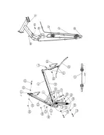
Страница 9: ...DIAGRAM 2 8...

Страница 10: ...ure them with two M10 x 3 Carriage Bolts 76 Washers 66 and M10 Aircraft Nuts 86 B Attach the Pulley Support Frame 97 to the Rear Vertical Beam Secure it with two M10 x 2 Carriage Bolts 75 one 4 x 2 Br...

Страница 11: ...d Post from the top Place the Rear Upper Frame 9 onto the Weight Glide Post 7 and Rear Vertical Beam 6 C Align the holes Secure the Rear Upper Frame to the Weight Glide Post with two M10 x 3 Allen Bol...

Страница 12: ...101 two Washers 66 and M10 Aircraft Nuts 86 C Insert a Cross Over Swivel Pulley Bracket 99 into the sleeve on the Left Upper Frame Secure it with one 7 8 x 5 8 Bushing and two M6 x Allen Screws 106 D...

Страница 13: ...erfly 11 to the hole on the Butterfly Base Secure it with one Lock Ring 56 1 Washer 67 M6 x 1 Allen Bolt 83 and M6 Aircraft Nut 85 D Attach the Butterfly Arm Pad 39 to the Right Butterfly Secure it wi...

Страница 14: ...CABLE LOOP DIAGRAM 13...

Страница 15: ...69 two Washers 66 and one M10 Aircraft Nut 86 C Draw the Cable around the Pulley then downward Attach a Single Floating Pulley Bracket 19 to the Cable Repeat Procedure B above to install a Pulley Let...

Страница 16: ...Nut 86 F Draw the Cable around the back Pulley then upward to the bracket underneath the Rear Upper Frame 9 Install a Single Small Pulley Bracket 98 to the bottom of Rear Upper Frame 9 Secure it with...

Страница 17: ......

Страница 18: ...ly installed in Step 8 E Install a Small Pulley to the Bracket Draw the Cable around the Small Pulley then downward to the open bracket on the Pulley Support Frame 97 F Install a Small Pulley to the b...

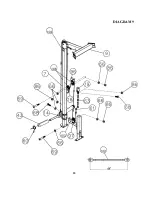
Страница 19: ...DIAGRAM 9 18...

Страница 20: ...he Pulley to the open bracket on the Weight Glide Base 8 C Install a Pulley to the bracket Draw the Cable around the Pulley then upward to the Double Floating Pulley Bracket 18 previously installed in...

Страница 21: ...atch hook forward on the Lifting Sleeve to secure its position on the selected holes on the Front Vertical Frames 3 Attach a Long Olympic Sleeve 44 to each end of the Weight Bar Attach a Spring Clip 6...

Страница 22: ...EXPLODED DIAGRAM 21...

Страница 23: ...top Frame 1 80 M8 x 2 Allen Bolt 6 27 Lifting Sleeve 1 81 M8 x 3 8 Allen Bolt 4 28 Weight Bar 1 82 M6 x 5 8 Philips Screw 1 29 Lat Bar 1 83 M6 x 1 Allen Bolt 2 30 Shiver Bar 1 84 Chrome Panel Screw 8...

Страница 24: ...lb resistance Lat Pull 100 10 lb plate creates 5 lb resistance Butterfly both arms 100 10 lb plate creates 10 lb resistance Left Cross Over 50 10 lb plate creates 5 lb resistance Right Cross Over 50 1...

Страница 25: ...t 37 2 Part 101 9x part 36 6 Part 17 1 Part 13 2 Part 33 1 Part 10 8x part 43 2 Part 44 1 Part 26 1 Part 24 1 Part 12 1x part 14 1 Part 96 1 Part 98 1 Part 18 2 Part 20 1x part 23 1 Part 31 1 Part 8 1...

Отзывы: