


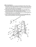


STEP 4 (See Diagram 4)
A.) Attach the Weight Glide Post (#7) onto the Weight Glide Base (#8). Secure it with four M10
x 1” Carriage Bolts (#74), Ø ¾” Washers (#66) and M10 Aircraft Nuts (#86).
B.) Slide the Sliding Weight Post (#14) onto the Chromed Post from the top. Place the Rear
Upper Frame (#9) onto the Weight Glide Post (#7) and Rear Vertical Beam (#6).
C.) Align the holes. Secure the Rear Upper Frame to the Weight Glide Post with two M10 x 3”
Allen Bolts (#71), four Ø ¾” Washers (#66), and two M10 Aircraft Nuts (#86). Do not tighten
the Nuts and Bolts yet.
D.) Secure the Upper Frame to the Rear Vertical Beam (#6) with two M10 x 2 ¾” Carriage
Bolts (#75),
∅
¾” Washers (#66) and M10 Aircraft Nuts (#86).
10
Содержание F-SM
Страница 4: ...3 SMITH MACHINE HARDWARE PACK...
Страница 5: ...4...
Страница 6: ...SMITH MACHINE HARDWARE PACK 5...
Страница 9: ...DIAGRAM 2 8...
Страница 14: ...CABLE LOOP DIAGRAM 13...
Страница 17: ......
Страница 19: ...DIAGRAM 9 18...
Страница 22: ...EXPLODED DIAGRAM 21...


