6
2. Panel Descriptions
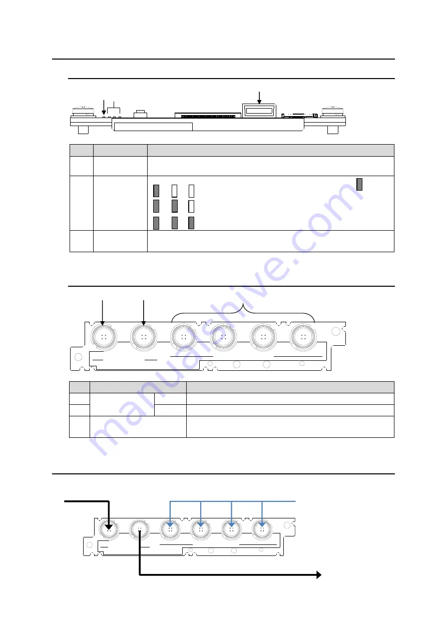
2-1. Front Panel
USF-1013MUX
No.
Name
Description
1
POWER
Lights green when power is supplied from USF frame and internal CPU is
functioning.
2
SDI-IN
Lights green when SDI signal is normally input. (Lights green )
: SD input
: 1.5G-SDI input
: 3G-SDI input
3
μ
SD card
connector
Used when upgrading USF-1013MUX software.
(
Do not insert
μ
SD card in normal operation.
)
2-2. Rear Panel
IN
OUT
3G/HD/SD SDI
USF-1013MUX
1/2
3/4
5/6
7/8
-LTC
DIGITAL AUDIO IN
No.
Name
Description
1
3G/HD/SD-SDI
IN
SD input connector
2
OUT
SDI output connector - Embeds selected audio channel.
3
DIGITAL AUDIO IN
1/2 to 7/8
4-pair AES/EBU input connector
7/8 can be used as LTC input connector by switching.
3. Connection
Connect peripheral devices referring to the drawing as shown below.
(1)
(3)
(2)
(1)
(3)
(2)
IN
OUT
3G/HD/SD SDI
USF-1013MUX
1/2
3/4
5/6
7/8
-LTC
DIGITAL AUDIO IN
Audio embedded SDI IN
DIGITAL AUDIO IN
SDI IN


