


42
10-9. How to Select Patterns
Wipe patterns are available for background and KEYER transitions. More than 150 preset
patterns are provided. This chapter explains how to select patterns for the transition, how to
check which pattern is currently selected and how to select patterns quickly using the Direct
Pattern function.
10-9-1. Selecting Patterns in the Menu
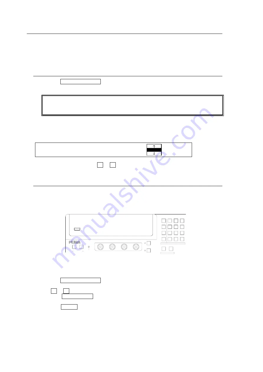
(1) Press the CLR/TRANS RATE button in the MENU/DIRECT PATT/EVENT/KEYPAD block
to display the [TRANS - BKGD] menu.
Users can also display the [TRANS - BKGD] menu by pressing the following buttons in
the Transition block: BKGD and KEYER in NEXT TRANSITION, MIX and WIPE in
TRANSITION TYPE and FADER LIMIT.
The number and the icon of the currently selected pattern are displayed under the
PATTERN item in the [TRANS - BKGD] menu. The letter M is added in front of the number
if the pattern is modified. (See section 10-9 "How to Select Patterns.")
TRANS : RATE : LIMIT :PATTERN : 1/6
BKGD : =30 : =100.0: =20 :
(2) To change the pattern, turn F3 or F4 to select a desired pattern.
10-9-2. Direct Pattern Function
The Direct Pattern Selection feature uses the number buttons on the keypad (0-9), to which
WIPE patterns previously registered can be recalled at the touch of one button. So it is useful
to assign frequently used patterns to number buttons. Up to 10 patterns can be registered.
To Register a Pattern:
(1) Press the CLR/TRANS RATE button in the MENU/DIRECT PATT/EVENT/KEYPAD block
to display the [TRANS - BKGD] menu.
(2) Turn F3 or F4 to select a pattern for registration.
(3) Press the DIRECT PATT button to the right of the Menu Display. The [DIRECT PATT]
menu is displayed and the keypad changes to DIRECT PATT mode.
(4) Press the STORE button.
(5) Press a number button. The selected pattern is saved to the number button.
(6) Repeat the steps (1) to (5) to register patterns.
USB MEMORY
NOR/REV
REV
F4
F3
F2
F1
PAGE
1
2
MENU/DIRECT PATT/EVENT/KEY PAD
ALARM
USER BUTTON
DIRECTION
7/SET UP
4/WIPE
1
8/STILL
5/P in P
2/KEYER
9/FILE
6/MATT
3/DSK
MENU
DIRECT PATT
±/EVENT
CLR/TRANS RATE
0
/RECALL
. (DOT)
ENT/STORE
Содержание HVS-300HS
Страница 1: ...HVS 300HS Digital Video Switcher HVS 30OU Operation Unit 1st Edition Rev 1 OPERATION MANUAL...
Страница 104: ......
Страница 108: ......


