background image

7


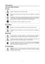
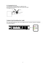
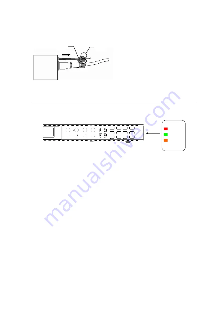
Unpluging the AC cord 

1)  Push the tab on the retaining up to unfasten the clip. 
2)  Push the tab on the ladder strap up and slide the clip back. 
3)  Unplug the AC cord. 


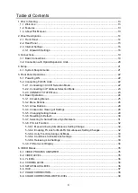
Colored Light Identification Label 

The colored light identification label can be attached to the front panel to assist in identifying 
colored light indication. 


1) 

2) 

POWER

ON

OFF

MU SEL

LOCK

FS SEL

FS LINK

EVENT

GENLOCK

FREEZE

TEST SIGNAL

BY-PASS

FAN ALARM

DC POWER

REMOTE CONTROL UNIT

FA-10RU

DISPLAY AREA

F1

F2

F3

F4

UNITY

UNITY

UNITY

UNITY

1

2

3

4

5

6

7

9

10

0

OPTION

8

PROC

EMB

CC

SETUP

CLIP

DWN MIX

BY-PASS
MAPPING

INPUT

AES

CLN SW

GAINI

OUTPUT

DELAY

ANC

ANALOG

SYSTEM

STATUS

VIDEO
AUDIO

MU /FS 

VIDEO 

AUDIO 

Содержание FA-10RU

Страница 1: ...FA 10RU for FA 505 Remote Control Unit 7th Edition Rev 3 Software Version 8 44 or higher OPERATION MANUAL ...

Страница 2: ...nged System Requirements Added Command Control 4 1 12 7 3 2019 06 17 Added commands to external command control 12 Software Version and Supported Options FA 10RU version Newly supported Feature Option Note FPGA1 1 00 FPGA2 1 00 Software 3 00 FA 505 FA 505UD FA 50PS Compatible FA 505 versions FPGA1 FPGA4 1 00 or higher FPGA5 3 00 or higher Software 1 00 or higher FPGA1 1 00 FPGA2 1 00 Soft 4 10 Com...

Страница 3: ...10UDC DC 12G Event Memory function USF 106UDC DC 12G event memory data can be saved by FA 10RU Factual errors corrected FPGA1 1 00 FPGA2 1 00 Soft 8 30 FA 96AHDR2 FA 9600 Version 3 support External command control MU SELECT command FPGA1 1 00 FPGA2 1 00 Soft 8 44 FS selection support MU Select command Status request command support FA 10RU versions can be seen in the FA 10RU INFORMATION menu see s...

Страница 4: ...ground the unit to gas lines units or fixtures of an explosive or dangerous nature Operation Hazard Do not operate the unit under hazardous or potentially explosive atmospheric conditions Doing so could result in fire explosion or other hazardous results Hazard Do not allow liquids metal pieces or other foreign materials to enter the unit Doing so could result in fire other hazards or a unit malfu...

Страница 5: ...nd disconnect the power cord to avoid potentially hazardous conditions If problems similar to the above occur contact an authorized service representative before attempting to operate the unit again Rack Mount Brackets Ground Terminal and Rubber Feet Caution To rack mount or ground the unit or to install rubber feet do not use screws or materials other than those supplied Doing so may cause damage...

Страница 6: ...t Explorer and Windows Media are either registered trademarks or trademarks of Microsoft Corporation in the United States and or other countries Firefox is a registered trademark of the Mozilla Foundation Dolby is a trademark of Dolby Laboratories All other trademarks are trademarks or registered trademarks of their respective owners Installing the AC Cord Retaining Clip Secure the AC cord with th...

Страница 7: ... identification label can be attached to the front panel to assist in identifying colored light indication 1 2 L L K T GENLOCK FREEZE TEST SIGNAL BY PASS FAN ALARM DC POWER REMOTE CONTROL UNIT FA 10RU DISPLAY AREA F1 F2 F3 F4 UNITY UNITY UNITY UNITY 1 2 3 4 5 6 7 9 10 0 OPTION 8 PROC EMB CC SETUP CLIP DWN MIX BY PASS MAPPING INPUT AES CLN SW GAINI OUTPUT DELAY ANC ANALOG SYSTEM STATUS VIDEO AUDIO ...

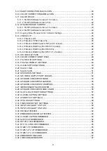
Страница 8: ... Basic Operations 24 5 3 1 Accessing Menus 25 5 3 2 Menu Buttons 26 5 3 3 Arrow Buttons 28 5 3 4 Consecutive Viewing of Settings 28 5 3 5 Changing Setting Values 29 5 3 6 Resetting to Default 30 5 3 7 Selecting 5 channel Frame Synchronizers 31 5 3 8 FS Link Function 32 5 3 8 1 Menus Allowing Simultaneous Setting Change 32 5 3 8 2 Enabling FS Link for Multi FS Simultaneous Setting Changes 32 5 3 8 ...

Страница 9: ...EO IN SETTINGS 48 6 18 FS SYNC FORMAT SETTINGS 49 6 19 CLEAN SWITCH SETTINGS 50 6 20 SALVO LOAD 50 6 21 SALVO SAVE 51 6 22 OPERATION SETTINGS 51 6 23 SDI VIDEO OUTPUT PORT ASSIGN 52 6 24 UP DOWN CONVERTER MODE 53 6 25 UP DOWN CONVERTER SIZE POS 55 6 26 UP DOWN CONVERTER CROPPING 55 6 27 IMPROVEMENT IN CONVERTER 56 6 28 UP DOWN CONVERTER SIDE COLOR 56 6 29 SLOT A D GPI FUNCTION SETTINGS 57 6 30 CLO...

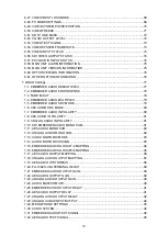
Страница 10: ...RC MODE 80 7 7 EMBEDDED AUDIO IN POLARITY 80 7 8 AES AUDIO IN POLARITY 81 7 9 ANALOG AUDIO IN POLARITY 81 7 10 SDI EMBEDDED AUDIO MONO SUM 81 7 11 AES AUDIO MONO SUM 82 7 12 ANALOG AUDIO MONO SUM 82 7 13 AUDIO DOWN MIX MODE 83 7 14 AUDIO DOWN MIX ASSIGN 83 7 15 EMBEDDED AUDIO GROUP1 2 MAPPING 84 7 16 EMBEDDED AUDIO GROUP3 4 MAPPING 85 7 17 AES AUDIO OUTPUT MAPPING 86 7 18 ANALOG AUDIO OUTPUT MAPPI...

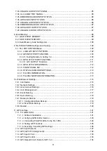
Страница 11: ...TPUT BRIGHTNESS 112 9 1 5 FRONT PANEL SET 112 9 1 6 STATUS LED MODE SETTINGS 113 9 1 7 FA 10RU INFORMATION 113 9 1 8 FA 10RU NETWORK INFORMATION 113 10 Web Browser Settings 114 10 1 Information 115 10 2 Network Settings 116 10 3 User Account Settings 116 10 4 Unit ID Assignment 117 10 5 Event Naming 117 10 6 Salvo Naming 118 10 7 Backup Restore 118 10 7 1 Configuration Data Backup 119 10 7 2 Event...

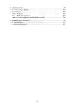
Страница 12: ...Communication Method 135 12 2 Command 135 12 2 1 Power On 135 12 2 2 MU Select Command 135 12 2 3 Connection Status Request Command Status 136 13 Specifications and Dimensions 137 13 1 Specifications 137 13 2 External Dimensions 137 ...

Страница 13: ...units via network This manual explains the FA 505 operations from FA 10RU units Refer to FA 10RU for FA 1010 Operation Manual for the FA 1010 operations Control over FA 505 via ethernet Up to 100 FA 505 units can be connected to be selected for control IP address FA 505 selection and control Simultaneous control over one FA 505 from five FA 10RU units Storage and recall of up to 100 events Storage...

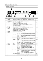
Страница 14: ...l input is present in the FA 505 FREEZE Lit green Flashing green 1 FREEZE is turned On for at least one FS in the FA 505 6 50 Unlit FREEZE is turned Off for all FSs 1 5 in the FA 505 TEST SIGNAL Lit green Flashing green 1 VIDEO or AUDIO TEST SIGNAL is turned On for at least one FS in the FA 505 6 53 7 31 7 34 Unlit VIDEO and AUDIO TEST SIGNAL is turned Off for all FSs 1 5 in the FA 505 BY PASS Lit...

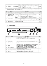
Страница 15: ...uble arrow button Used to move between menus Indicators light up to indicate the accessible direction 5 3 9 Menu buttons Used to select menus 5 3 1 5 3 2 2 2 Rear Panel No Name Description Ref 1 TO MU A LAN connector for FA 505 control Set the unique IP address and connect to the network 3 2 GPI 1 GPI 3 Used to connect an FA AUX30 or external expansion switch panel s 3 2 9 1 1 9 1 2 9 1 3 11 3 FAN...

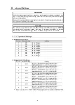
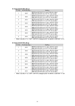
Страница 16: ...OFF Do not change 5 OFF Do not change 6 OFF Do not change 7 OFF Do not change 8 OFF Do not change Dipswitch S101 Settings Pin No Default setting Setting 1 OFF OFF Sets GPI OUT1 to open collector output ON Sets GPI OUT1 to 5V TTL level output 2 OFF OFF Sets GPI OUT2 to open collector output ON Sets GPI OUT2 to 5V TTL level output 3 OFF OFF Sets GPI OUT3 to open collector output ON Sets GPI OUT3 to ...

Страница 17: ...to 5V TTL level output Refer to section 11 3 GPI 1 GP I3 Pin Assignments for details on GPI OUT 9 16 Dipswitch S103 Settings Pin No Default setting Setting 1 OFF OFF Sets GPI OUT17 to open collector output ON Sets GPI OUT17 to 5V TTL level output 2 OFF OFF Sets GPI OUT18 to open collector output ON Sets GPI OUT18 to 5V TTL level output 3 OFF OFF Sets GPI OUT19 to open collector output ON Sets GPI ...

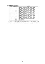
Страница 18: ...UT27 to open collector output ON Sets GPI OUT27 to 5V TTL level output 4 OFF OFF Sets GPI OUT28 to open collector output ON Sets GPI OUT28 to 5V TTL level output 5 OFF OFF Sets GPI OUT29 to open collector output ON Sets GPI OUT29 to 5V TTL level output 6 OFF OFF Sets GPI OUT30 to open collector output ON Sets GPI OUT30 to 5V TTL level output 7 OFF Do not change 8 OFF Do not change Refer to section...

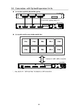
Страница 19: ... 5 1 2 6 CLIP DWN MIX 3 OUT PUT DE LAY 7 STA TUS 0 BY P ASS MAP PING 4 OPT ION 8 VIDEO AUDIO ON OFF POW ER LOCK FS LINK MU SEL FS SEL EV ENT GENLOCK FANALARM FREEZE DCPOWER TEST SIGNAL BY PASS DISPLAY AREA F A 1 0 R U R E M O T E C O N T R O L U N I T F1 UN ITY F2 UNITY F3 UNITY F4 UN ITY PROC EMB INP UT A ES A NC ANA LOG CC SE TUP CLN SW GAIN 10 SYSTEM 9 5 1 2 6 CLIP DWN MIX 3 OUT PUT DE LAY 7 ST...

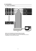
Страница 20: ... See section 11 GPI Interface for details on GPI connectors GPI1 GPI2 GPI3 FA AUX30 FA AUX30 supplied cables x 3 AC100 240V 50 60Hz IN GPI3 GPI2 GPI1 TO MU 10 100 1000BASE T FA 10RU FS1 FS2 FS3 FS4 FS5 FS6 FS7 FS8 FS9 FS10 Connect to GPI1 GPI3 connector AC100 240V 50 60Hz IN GPI3 GPI2 GPI1 TO MU 10 100 1000BASE T FA 10RU ...

Страница 21: ...l Core 2 Duo processor 2GHz or higher Web browser Internet Explorer 11 Firefox 54 Chrome 59 Opera 46 Internet Explorer 11 Firefox 24 Chrome 59 Opera 46 Free memory 2GB or more 4GB or more Display Resolution of 1024 768 pixels or higher Must be capable of full color 24 bit display Network port Ethernet at least one port 100BASE TX 1000BASE T Network cable 100BASE TX Category 5 or better 1000BASE T ...

Страница 22: ...address 5 2 1 Connecting in Unit ID Selection Mode Pressing the MU SEL button opens the UNIT ID MU SELECT menu UNIT ID MU SELECT P801 F1 Main Unit ID 2 IP Address 192 168 0 10 Port 50011 NAME FA 505 Default Push F3 Unity SW Connect to Main Unit Push F4 Unity SW Cancel Turn F1 and select the FA 505 to be connected from Main Unit IDs 1 through 100 The IP address TCP port number and unit name will be...

Страница 23: ...cel the selection press the UNITY button under F4 CANCEL Cancelling the connection returns the settings to their last state before change The MU ID name will be displayed under NAME if there is a name assigned to the IP address 5 2 3 CONNECT STATE Menu Connections with FA 505 units can be viewed in the CONNECT STATE menu MU CONNECT STATE P803 IP Address 192 168 0 10 Port 50011 State Connected ID F...

Страница 24: ... 2 Menu Buttons with an asterisk IMPORTANT Make sure that the LOCK indicator on the front panel is turned off before starting an operation If the LOCK indicator is lit orange all operations on the front panel except the LOCK button are disabled Press and hold the MU SEL LOCK button to enable operation The description in Basic Operation starts based on an established connection To establish a conne...

Страница 25: ...rameters that can be changed using controls F1 to F4 in the page The 0 STATUS button will blink green during error condition when a video menu is selected and 4K Input Mode is set to Auto or 2SI See Sec 6 57 PAYLOAD ID INPUT STATUS for more details Menu Buttons FS1 Name FS 1 VIDEO PROCESS AMPLIFIER P501 F1 F3 Video 100 0 Y 100 0 C 100 0 Setup Black 0 0 Hue 0 0deg In the above example the 1 PROC EM...

Страница 26: ...N POLARITY SDI EMBEDDED AUDIO MONO SUM AES AUDIO MONO SUM 3 ANALOG AUDIO MONO SUM 4 3 CLIP DWN MIX VIDEO CLIP AUDIO DOWN MIX MODE AUDIO DOWN MIX ASSIGN 4 BY PASS MAPPING SDI VIDEO BY PASS COLOR CORRECTION BY PASS EMBEDDED AUDIO GROUP1 2 MAPPING EMBEDDED AUDIO GROUP3 4 MAPPING AES AUDIO OUTPUT MAPPING 3 ANALOG AUDIO OUTPUT MAPPING 4 5 INPUT AES FS VIDEO IN SETTINGS FS SYNC FORMAT SETTINGS AES AUDIO...

Страница 27: ...T STATUS PAYLOAD ID INPUT STATUS 6 MAIN UNIT ALARM INFORMATION MAIN UNIT VERSION INFORMATION OPTION VERSION INFORMATION OTHER OPTION INFORMATION EMBEDDED AUDIO INPUT STATUS AES AUDIO INPUT STATUS 3 ANALOG AUDIO INPUT STATUS 4 EMBEDDED AUDIO OUTPUT STATUS AES AUDIO OUTPUT STATUS 3 ANALOG AUDIO OUTPUT STATUS 4 VIDEO AUDIO VIDEO menus AUDIO menus Menus in which settings can be changed for FS1 and FS2...

Страница 28: ...for details on Normal and Live Safe mode switching 5 3 4 Consecutive Viewing of Settings Holding down the double up or down arrow button enables you to sequentially display menus across menu categories assigned to menu buttons Order of Consecutive Menu Display VIDEO Menus Lit green Holding down the double down arrow button consecutively displays menu pages in the menu list from VIDEO PROCESS AMPLI...

Страница 29: ...firmation such as FS VIDEO IN SETTINGS will request confirmation when the parameter is changed Example procedure Pressing the 6 INPUT AES button while the button is in VIDEO menu selection mode lit green by pressing the VIDEO AUDIO button displays the FS VIDEO IN SETTING menu To change the input video to FS1 turn F1 To change the input video to FS2 turn F2 If any menu item is changed the double ar...

Страница 30: ... mode The UNITY indicator light goes off when the setting value has changed from default If the UNITY button is pressed while the light is off double arrow buttons and the changed menu item start to blink to request confirmation Pressing the double down arrow button will resets the value to default and the UNITY indicator lights up Pressing the double up arrow button cancels the reset the setting ...

Страница 31: ... 5 serve as FSs 1 to 5 to be selected Select an FS number using the buttons then FS1 Name FS 1 changes to show the selected FS Settings for the selected FS can be changed using control knobs FS1 to FS4 FS Name List as shown below can be viewed while pressing the VIDEO AUDIO button FS1 Name FS 1 FS1 VIDEO PROCESS AMPLIFIER P501 FS Name List FS1 FS 1 FS2 FS 2 FS3 FS 3 FS4 FS 4 FS5 FS 5 Pressing eith...

Страница 32: ...king FS1 is displayed in the menu display Selectable menu buttons 2 to 5 FS2 to FS5 also blink Menu buttons that corresponds to FSs that cannot be linked are unlit In the below example FS2 and FS3 are linked to FS1 FS names set for each FS are displayed only while buttons FS1 to FS5 are pressed Linked FSs are displayed The below example is the linked setting in the VIDEO PROCESS AMPLIFIER menu FS1...

Страница 33: ...ction during Link mode can be set to either affect only the displayed FS or all linked FSs Setting to Unlinked Unity under Unity as described in section 6 22 OPERATION SETTINGS sets the Unity function to be effective only for the displayed FS Conversely setting to Linked Unity sets it to be effective on all linked FSs 5 3 8 4 Conditions to Enable Link Settings The FS to be linked must have the bel...

Страница 34: ...F SDI2 I O OFF The FS NAME List as shown below can be displayed by pressing the FS SEL FS LINK button while displaying a menu for which the FS selection is not displayed in the top row SDI VIDEO BY PASS P515 FS Name List FS1 FS 1 FS2 FS 2 FS3 FS 3 FS4 FS 4 FS5 FS 5 ...

Страница 35: ...o adjust the color phase for the selected FS To change the FS selection to set settings refer to section 5 3 7 Selecting 5 channel Frame Synchronizers To simultaneously change settings of multiple FSs refer to section 5 3 8 FS Link Function If the selected FS bypasses the Color Correction process this menu is disabled Change COLOR CORRECTION BY PASS to Operate then reset the parameter See section ...

Страница 36: ...Link setting mode F1 is displayed for the key FS of the link setting To change the FS selection to set settings refer to section 5 3 7 Selecting 5 channel Frame Synchronizers To simultaneously change settings of multiple FSs refer to section 5 3 8 FS Link Function If the selected FS bypasses the Color Correction process this menu is disabled Change COLOR CORRECTION BY PASS to Operate then reset th...

Страница 37: ...ed for the selected FS In Link setting mode F1 is displayed for the link setting key FS of the link setting To change the FS selection to set settings refer to section 5 3 7 Selecting 5 channel Frame Synchronizers To simultaneously change settings of multiple FSs refer to section 5 3 8 FS Link Function If the selected FS bypasses the Color Correction process this menu is disabled Change COLOR CORR...

Страница 38: ...ed The lower threshold is fixed to 0 The value of 100 is based on the OETF Maximum Input setting CC Mode Balance Balance Differential Sepia Allows you to select a color correction mode for the selected FS Balance RGB signal correction mode Allows you to adjust the white balance Gray scale can be changed by adjusting R G and B levels Differential Color difference signal mode Allows you to adjust co...

Страница 39: ...R 100 0 G 100 0 B 100 0 FS4 R 100 0 G 100 0 B 100 0 FS5 R 100 0 G 100 0 B 100 0 Parameter Default Setting range Steps Description White Level RGB 100 0 0 0 200 0 0 5 Allows you to adjust R G and B components of the white level separately for the selected FS F4 allows you to adjust R G and B components simultaneously The FS number of the selected FS blinks FS numbers of linked FSs also blink Displa...

Страница 40: ...n process this menu is disabled Change COLOR CORRECTION BY PASS to Operate then reset the parameter See section 6 16 6 10 COLOR CORRECTION GAMMA LEVEL FS1 Name FS 1 COLOR CORRECTION GAMMA LEVEL P510 FS1 R 100 0 G 100 0 B 100 0 FS2 R 100 0 G 100 0 B 100 0 FS3 R 100 0 G 100 0 B 100 0 FS4 R 100 0 G 100 0 B 100 0 FS5 R 100 0 G 100 0 B 100 0 Parameter Default Setting range Steps Description Gamma Level...

Страница 41: ...ls from YPbPr to RGB color matrix values corresponding to this setting is used Transfer Matrix Rec ITU R BT 709 Standard dynamic range Rec ITU R BT 2020 High dynamic range User1 User5 Use Transfer Matrix data in gmt files SD SDI inputs are always processed in Rec 601 Gamut Out Gamma Curve OETF By pass By pass SDR 2 2 Rec 1886 SDR 2 4 Rec 1886 HLG SG 1 0 HLG SG 1 2 HLG SG 1 4 ST2084 Narrow ST2084 S...

Страница 42: ...and percentage value for other cases 6 11 2 FA 505 Software Version 2 03 FS1 Name FS 1 COLOR SPACE P512 F1 In Gamma Curve EOTF By pass In Color Space Rec 709 Out Gamma Curve OETF By pas Out Color Space Rec 709 ST 2084 PQ Range 64 0 Parameter Default Setting range Steps Description In Gamma Curve EOTF By pass By pass Rec 709 Rec 1886 Hybrid Log Gamma SMPTE ST 2084 S Log3 Canon Log 2 Allows you to s...

Страница 43: ...linked FSs also blink To change the FS selection to set settings refer to section 5 3 7 Selecting 5 channel Frame Synchronizers 6 12 2 FA 505 Software Version 2 03 FS1 Name FS 1 DYNAMIC RANGE CONTROL P513 EOTF Maximum Output 1 0 OETF Maximum Input 1 0 F1 Dynamic Range 1 0 Parameter Default Setting range Steps Description Dynamic Range Variable 0 5 65 0 0 5 Allows you to adjust the RGB color range ...

Страница 44: ...ubmenu to be copied Source FS1 FS1 FS10 Selects an FS for copy source Destination FS2 FS1 FS10 Selects an FS for copy destination Press F4 Unity to execute data copy Parameters to be copied FA 1010 9500 9520 FA 505 V1 21 or less FA 505 V2 03 FA 505 V2 10 MODE setting Parameters Parameters Parameters Video Process Video Level Y Level Chroma Level Setup Black Level Hue Same as at left Same as at lef...

Страница 45: ...ignal upper threshold Black Level Y Black Clip 7 5 7 5 50 0 0 5 Allows you to set the Y signal lower threshold Chroma Level PbPr Chroma Clip 111 0 50 0 111 0 0 5 Allows you to set both the upper and lower thresholds of PbPr signals 6 14 3 If Mode is RGB Clip FA 505 V2 13 or later FS1 Name FS 1 VIDEO CLIP P514 F1 Mode RGB Clip White Black Input Clip F1 100 0 F2 0 0 Output Clip F1 100 0 F2 0 0 Knee ...

Страница 46: ...eating the In Peak Luminance value as a 100 Output Clip 100 0 50 0 150 0 5 Allows you to set the input maximum level Enter the value by treating the Out Peak Luminance value as a 100 Knee Point 100 0 50 0 150 0 5 Allows you to set the knee clip point Black Clip Input Clip 0 0 50 0 50 0 0 5 Allows you to set the input minimum level Enter the value by treating the Reference White value as a 100 Outp...

Страница 47: ...r Default Setting range Steps Description White Level RGB White Clip 300 0 50 0 300 0 0 5 Allows you to set the upper threshold of RGB color space Black Level RGB Black Clip 200 0 200 0 50 0 0 5 Allows you to set the lower threshold of RGB color space To change the FS selection to set settings refer to section 5 3 7 Selecting 5 channel Frame Synchronizers To simultaneously change settings of multi...

Страница 48: ...e item to be changed using the single arrow buttons 6 17 FS VIDEO IN SETTINGS FS VIDEO IN SETTINGS P519 F1 FS1 SDI1 Input FS2 SDI2 Input FS3 SDI3 Input FS4 SDI4 Input FS5 SDI5 Input F4 Unity reset s all settings to default Parameter Default Setting range Description FS1 FS5 Respective FSs 1 5 SDI1 Input SDI5 Input SDI1 Input SDI5 Input Allows you to assign input video signals to respective FSs The...

Страница 49: ...format for each FS 2 2x1080 59i LVLB 3 1080 29p 1080 23p If VIDEO SYSTEM FRAME RATE is 24 25 30 50 60 fps 1 625 50 1080 50i 720 50p 1080 24PsF 1080 50p Level A 1080 50p Level B 2 2x1080 50i LVLB 3 1080 24p 1080 25p 4 1080 30p 1080 60p Level A Move the F1 F2 indication to the item to be changed using the single arrow buttons 1 VIDEO SYSTEM FRAME RATE can be set in the VIDEO SYSTEM FRAME RATE menu s...

Страница 50: ... the single arrow buttons Set all matrices then set Front Operation to Live Safe in the OPERATION SETTINGS menu to apply the settings 6 20 SALVO LOAD SALVO LOAD P526 Destination1 Source FS1 Output Destination2 Source FS2 Output Destination3 Source FS3 Output Destination4 Source FS4 Output Destination5 Source FS5 Output F1 No 1 Name Salvo1 F2 Unit FA 10RU Press F3 Unity to start Param eter Default ...

Страница 51: ...A 10RU FA 10RU FA 505 Allows you to select a unit to which to save the Salvo setting Set Destination1 5 No and Unit then press the F3 Unity button to save the matrices Displays Saving salvo data while the Salvo setting is being saved Move the F1 F2 indication to the item to be changed using the single arrow buttons When the SALVO SAVE menu is accessed Destination1 5display the current output matri...

Страница 52: ...scription OUT1a b OUT5a b Respective OUTs 1a b 5a b Router Out1 Router Out5 Router Out1 5 Allows you to assign Clean SW ROUTE output signals to SDI connectors OUT1a 1b SDI OUT 5a 5b respectively The F4 Unity button allows you to reset all FS inputs to default Move the F1 F2 indication to the item to be changed using the single arrow buttons To change the FS selection to set settings refer to secti...

Страница 53: ...I 1080p format Aspect 1 SD AFD 4 3 AFD 4 3 AFD ALT 4 3 AFD 16 9 AFD ALT 16 9 4 3 L 16 9 T 4 3 L 14 9 T 4 3 L 16 9 4 3 F 4 3 4 3 L16 9PRTD 4 3 L 14 9 4 3 F ALT14 9 4 3 L ALT14 9 4 3 L ALT 4 3 16 9 L 16 9 16 9 F 16 9 16 9 P 4 3 16 9 F PRTD 16 9 P 14 9 16 9P ALT 14 9 16 9F ALT14 9 16 9F ALT4 3 Selectable aspect ratio settings when Converter Mode is set to SD 4 3 AFD 4 3 AFD ALT 16 9 AFD and 16 9 AFD ...

Страница 54: ... 2x1080 59i By pass 2x1080 59i By pass 2x1080 59i By pass 2x1080 59i By pass PAL formats 625 50 625 50 1080 50i 720 50p 1080 24PsF 1080 24p 1 1080 25p 1 1080 30p 1 1080 50p 1 1080 60p 1 1080 50i 625 50 1080 50i 720 50p 1080 50i BY PASS 1080 25p 1080 50p 720 50p 625 50 1080 50i 720 50p 720 50p BY PASS 1080 25p 1080 50p 1080 60p 625 50 1080 60p By pass 1080 60p By pass 1080 60p By pass 1080 30p 1080...

Страница 55: ... change one of their setting values setting ranges of other parameters will also change FS SYNC FORMAT SETTINGS see section 6 18 UP DOWN Converter Mode see section 6 24 If the Convert Mode is set to BY PASS Resize and Position cannot be changed and the Unadjustable is displayed Also it cannot be changed if the conversion is set to the formats indicated as BY PASS in the Conversion Table see the pr...

Страница 56: ...alias H Normal Weak 8 1 Normal Strong 1 8 Performs horizontal anti aliasing for the output video image Weak 8 to Strong 8 low to high Antialias V Normal Weak 8 1 Normal Strong 1 8 Performs vertical anti aliasing for the output video image Weak 8 to Strong 8 low to high Enhance Level0 Level 0 8 Sharpens the output video image Level 0 to 8 low to high The Antialias cannot be changed if Converter Mod...

Страница 57: ...utput signal level is Low in an Alarm state Invert The Output signal level is High in an Alarm state 1 See the GPI Input settings list for details 2 See the GPI Output settings list for details Also see the FA 505 Operation Manual for details on GPI functions Move the F1 indication to the item to be changed using the single arrow buttons Changes will be applied to the FA 505 when the F2 Unity butt...

Страница 58: ...Odd Outputs when Freeze Mode is set to Odd for all FSs 1 5 All Freeze Even Outputs when Freeze Mode is set to Even for all FSs 1 5 FS 1 5 Freeze On Off Outputs when Freeze is set to On for the subject FS All Freeze On Off Outputs when Freeze is set to On for all FSs 1 5 SDI 1 5 By pass On Off Outputs when By pass is set to On for the subject FS All By pass On Off Outputs when By pass is set to On ...

Страница 59: ...Hz Outputs when Audio Test Signal is set to 1kHz for the subject AES Audio Test Signal Analog Off Outputs when Audio Test Signal is set to Off for the Analog audio Audio Test Signal Analog 500Hz Outputs when Audio Test Signal is set to 500Hz for the Analog audio Audio Test Signal Analog 1kHz Outputs when Audio Test Signal is set to 1kHz for the Analog audio Audio Test Signal All Off Outputs when A...

Страница 60: ...ings refer to section 5 3 7 Selecting 5 channel Frame Synchronizers 6 32 AFD LOSS SETTINGS FS1 Name FS 1 AFD DETECT SETTINGS P558 F1 S2016 3 SD Remove S2016 3 HD Remove RP186 VI SD Remove WSS SD Remove This menu allows you to specify an aspect ratio processing for use if AFD data cannot be detected Parameter Default Setting range Description S2016 3 SD Remove Remove Hold 4 3 L 16 9 T 4 3 L 14 9 T ...

Страница 61: ...he built in converter FA 505UD 4 3 F 4 3 is applied But no VI AFD data is embedded in SDI outputs WSS SD Remove Remove Hold 4 3 BOX 16 9 T 4 3 BOX 14 9 T 4 3 BOX 16 9 C 4 3 F 4 3 4 3 BOX 4 3 C 4 3 BOX 16 9 C 4 3 F 14 9 16 9 F 16 9 Anamorphic Select an AFD code if BT1119 2 WSS data cannot be detected in SD SDI inputs The selected AFD code is used for conversion process Remove If the automatic aspec...

Страница 62: ... Overwrite V Pass FS3 Mode H V H Overwrite V Pass FS4 Mode H V H Overwrite V Pass FS5 Mode H V H Overwrite V Pass Parameter Default Setting range Description FS1 to FS5 Mode H V H V Detail Allows you to select a processing mode for ancillary data for each FS H V Allows you to select overwrite pass or blank the HANC and VANC spaces on output signals Detail Deletes all exiting H V ANC data sources f...

Страница 63: ...A708 1080i PsF Line9 EMB Disable CEA708 720p Line9 EMB Disable CEA708 3G LevelA Line9 EMB Disable CEA708 3G LevelB Line9 EMB Disable This menu allows you to specify the line s for embedding Closed Caption data onto SDI output This page is enabled only when ANC Mode P564 is set to Detail Parameter Default Setting range Description CEA605 525 60 Line Line21 284 To embed data source set EMB to Enable...

Страница 64: ...vel A Line 9 9 to 41 Embedded Disable Disable Enable 3G Level B Line 9 571 9 571 to 20 582 Embedded Disable Disable Enable To change an FS to be monitored refer to section 5 3 7 Selecting 5 channel Frame Synchronizers 6 40 RP186 VI AFD EMBEDDED FS1 Name FS 1 RP186 VI AFD EMBEDDED P568 525 60 F1 Field1 Line14 F2 Field2 Line277 525 60 Embedded Disable 625 50 F1 Field1 Line11 F2 Field2 Line324 625 50...

Страница 65: ... 3 Full format 4 3 is embedded instead of the unsupported aspect ratio To change the FS selection to set settings refer to section 5 3 7 Selecting 5 channel Frame Synchronizers 6 42 S12M 1 VITC EMBEDDED FS1 Name FS 1 S12M 1 VITC EMBEDDED P570 525 60 F1 Line14 277 F2 Embedded Disable 625 50 Line19 332 Embedded Disable This menu allows you to specify the line s for embedding S12M 1 VITC data onto SD...

Страница 66: ... FS selection to set settings refer to section 5 3 7 Selecting 5 channel Frame Synchronizers 6 44 S12M 1 ATC LTC EMBEDDED FS1 Name FS 1 S12M 1 ATC LTC EMBEDDED P572 525 60 F1 Line12 F2 Embedded Disable 625 50 F1 Line8 F2 Embedded Disable 1080i PsF Line10 Embedded Disable 720p Line10 Embedded Disable 3G LevelA Line10 Embedded Disable 3G LevelB Line10 Embedded Disable This menu allows you to specify...

Страница 67: ...re the LTC IN OUT connector on the rear panel as an input or output Time If LTC Port is set to Input the current status of timecode input to the connector is displayed If LTC Port is set to Output the counter of the built in Timecode Generator is displayed Move the F1 F2 indication to the item to be changed using the single arrow buttons 6 46 TIMECODE GENERATOR TIMECODE GENERATOR P576 Time 00 00 0...

Страница 68: ...S FS2 5 Enable 4k Input Mode Auto 2SI Out Payload ID 2SI Parameter Default Setting range Description Sync Mode Frame Frame Line AVDL Line Minimum Frame Adjusts horizontal and vertical timings of signals based on the adjusted FA 505 system phases Effective on both synchronous and asynchronous signals Line AVDL Line Minimum Adjusts horizontal and vertical timings of signals listed in the Adjustable ...

Страница 69: ...ine SQD or 2SI SQD Regards 4K input as SQD 2SI Regards 4K input as 2SI When 2SI is selected an error will be indicated by the 0 STATUS flashing if an FS channel FS2 FS5 has no 2SI identification code or 2SI channel correspondence is mismatched between Payload ID and FS channel information See Sec 6 57 PAYLOAD ID INPUT STATUS for details on errors 4k Output Mode 2 4 2SI 2SI SQD Selects SQD or 2SI t...

Страница 70: ...5H to 2 5H 8H to 2 5H 3 3H to 2 3 H 2H 700 clk 1080 50p Level A B 3 5H to 2 5H 8H to 2 5H 3 243H to 2 43 H 2H 1150 clk 1080 59p Level B A 1 5H to 0 5H 6H to 0 5H 1 3H to 0 3 H 700 clk 1080 50p Level B A 1 5H to 0 5H 6H to 0 5H 1 25H to 0 25 H 700 clk 525 60 1 5H to 0 5H 6H to 0 5H 1 4H to 0 4 H 700 clk 625 50 1 5H to 0 5H 6H to 0 5H 1 4H to 0 4 H 700 clk IMPORTANT Note that 1080 59p or 1080 50p Le...

Страница 71: ...On Off Off F2 Freeze Mode Frame F3 Strobe Freeze Off F4 All FS Freeze Off Input Video 1080 59i Parameter Default Setting range Description Freeze Off Off On Allows you to turn Freeze On Off for each FS Freeze Mode Frame Frame Odd Even Allows you to select an operation mode for Freeze Displays Unadjustable if no signal or a progressive signal is input to the FS Strobe Freeze Off Off 1 255 Allows yo...

Страница 72: ...T LEVEL P584 F1 FS1 Follow Input FS2 Follow Input FS3 Follow Input FS4 Follow Input FS5 Follow Input Parameter Default Setting range Description FS1 FS5 Follow Input Follow Input Level A Level B Allows you to select a 3G Level Level A B for each FS Follow Input The 3G SDI input signal Level will not be changed and output level will be the same Follow Input converts video to 3G Level A if it is oth...

Страница 73: ...FRAME RATE P586 F1 Frame Rate 23 98 29 97 59 94 fps __________________________________________ Carefully change Frame Rate __________________________________________ Parameter Default Setting range Description Frame Rate 23 98 29 97 59 94 fps 23 98 29 97 59 94 fps 24 25 30 50 60 fps Allows you to select a video system frame rate Note Carefully adjust the setting to prevent the input output video s...

Страница 74: ...Byte 4 in the payload ID information Payload Identification Codes for 3G SDI Level A are located in Bit 7 6 of Byte 4 Bit 7 6 0 3G SDI Link1 Corresponds to FS2 Bit 7 6 1 3G SDI Link2 Corresponds to FS3 Bit 7 6 2 3G SDI Link3 Corresponds to FS4 Bit 7 6 3 3G SDI Link4 Corresponds to FS5 Payload Identification Code for 3G SDI Level B is located in Bit 7 5 of Byte 4 Bit 7 5 0 Data stream one on 3G SDI...

Страница 75: ...of the connected FA 505 Normal All fans are operating normally Stopped One or more fans have failed Power Off the unit and consult your reseller DC POWER1 DC POWER2 Displays the status of Power Supply unit 1 and 2 Normal Power supply is normal Abnormal A power failure has occurred Power Off the unit and consult your reseller No indication if an FA 505PS is not installed 6 59 MAIN UNIT VERSION INFO...

Страница 76: ...led in option slots A to D of the connected FA 505 Slots A to D to be displayed can be selected with the same procedure as that to select FS 1 to 5 6 61 OTHER OPTION INFORMATION UNIT VERSION INFORMATION P604 FA 505PS Installed FA 505UD Installed Parameter Default Setting range Description FA 505PS Displays whether the FA 505PS is installed or not FA 505UD Displays whether the FA 505UD is installed...

Страница 77: ...Sync SDI Audio Clock Allows you to select audio clock signal to use for de embedding and processing audio data in HD SDI input signal Auto De embeds HD SDI embedded audio data using the audio clock phase data in the embedded audio Synchronous and asynchronous embedded audio signals from 4 audio groups can be de embedded separately Audio data will be processed as synchronous data if the audio clock...

Страница 78: ...ensitive Mutes when a change on channel status or EDP Extended Data Packet presence only for SD SDI as well as the above items is detected Move the F1 F2 indication to the item to be changed using the single arrow buttons 7 3 FADE IN OUT FADE IN OUT P613 F1 FS1 Disable FS2 Disable FS3 Disable FS4 Disable FS5 Disable Parameter Default Setting range Description FS1 FS5 Disable Disable Enable Disable...

Страница 79: ...Input CH 7 8 Audio Group 3 Auto Auto Reference Input CH 9 10 Input CH 11 12 Audio Group 4 Auto Auto Reference Input CH 13 14 Input CH 15 16 To change the FS selection to set settings refer to section 5 3 7 Selecting 5 channel Frame Synchronizers 7 5 EMBEDDED AUDIO SRC MODE FS1 Name FS 1 EMBEDDED AUDIO SRC MODE P616 F1 CH 1 2 Auto F2 CH 3 4 Auto CH 5 6 Auto CH 7 8 Auto CH 9 10 Auto CH11 12 Auto CH1...

Страница 80: ...s Useful for the irregular PCM signal with the NON PCM audio channel status indication However real NON PCM signals cannot be output properly To change the slot selection to set settings select a slot from A to D AES A to AES D in the same procedure described in section 5 3 7 Selecting 5 channel Frame Synchronizers Displayed if an FA 10AES BL FA 10AES UBL is installed in slot A D 7 7 EMBEDDED AUDI...

Страница 81: ... IN POLARITY P620 F1 CH1 Normal F2 CH2 Normal F3 CH3 Normal F4 CH4 Normal Parameter Default Setting range Description CH1 CH4 Normal Normal Invert Allows you to set polarity per analog audio channel for the FA 10ANA AUD card installed in slot A D INV Invert Reverses polarity Displayed if the FA 10ANA AUD is installed in slot A D 7 10 SDI EMBEDDED AUDIO MONO SUM FS1 Name FS 1 SDI EMBEDDED AUDIO MON...

Страница 82: ...lect a slot from A to D AES A to AES D in the same procedure described in section 5 3 7 Selecting 5 channel Frame Synchronizers Displayed if an FA 10AES BL FA 10AES UBL is installed in slot A D 7 12 ANALOG AUDIO MONO SUM ANALOG AUDIO MONO SUM P624 F1 CH 1 2 Stereo F2 CH 3 4 Stereo Parameter Default Setting range Description CH 1 2 CH 3 4 Stereo Stereo Monaural Monaural Outputs each FA 10ANA AUD an...

Страница 83: ...ons To change the FS selection to set settings refer to section 5 3 7 Selecting 5 channel Frame Synchronizers Audio levels when Master Level is set to Auto Surround Mix Level Downmix Mode 3dB 6dB 9dB 0 dB Stereo Approx 7 7dB Approx 6 9dB Approx 6 3dB Approx 4 6dB Surround Approx 9 9dB Approx 8 7dB Approx 7 7dB Approx 4 6dB Monaural Approx 12 9dB Approx 12 0dB Approx 11 4dB Approx 9 5dB 7 14 AUDIO ...

Страница 84: ...D In CH8 Analog In CH1 Analog In CH4 Allows you to select audio channels to embed to embedded audio group 1 2 for each FS Displays the FS number FS1 to FS5 of the selected FS Control knobs F1 and F3 allow you to navigate audio channels one by one Control knobs F2 and F4 allow you to navigate audio channels in block units Move the F1 F3 indication to the item to be changed using the single arrow bu...

Страница 85: ...AES D In CH8 Analog In CH1 Analog In CH4 Allows you to select audio channels to embed to embedded audio group 3 4 for each FS Displays the FS number FS1 to FS5 of the selected FS Control knobs F1 and F3 allow you to navigate audio channels one by one Control knobs F2 and F4 allow you to navigate audio channels in block units Move the F1 F3 indication to the item to be changed using the single arro...

Страница 86: ... Analog In CH1 Analog In CH4 Allows you to select audio channels to output to AES output in option slot A D Displays the FS number FS1 to FS5 of the selected FS Control knobs F1 and F3 allow you to navigate audio channels one by one Control knobs F2 and F4 allow you to navigate audio channels in block units Move the F1 F3 indication to the item to be changed using the single arrow buttons To chang...

Страница 87: ...llows you to select an audio channel to output to the FA 10ANA AUD analog audio output Displays the FS number FS1 to FS5 of the selected FS Control knobs F1 and F3 allow you to navigate audio channels one by one Control knobs F2 and F4 allow you to navigate audio channels in block units Move the F1 F3 indication to the item to be changed using the single arrow buttons To change the FS selection to...

Страница 88: ...n 5 3 7 Selecting 5 channel Frame Synchronizers Displayed if the an FA 10AES BL FA 10AES UBL is installed in slot A D 7 20 FA 10AES UBL TERMINAL IN OUT FA 10AES UBL TERMINAL IN OUT P637 OP CH1 2 CH3 4 OP CH5 6 CH7 8 F1 A Input F2 A Input B Not Installed B Not Installed C Not Installed C Not Installed D Not Installed D Not Installed Parameter Default Setting range Description OP A to OP D Input Inp...

Страница 89: ...ion 5 3 7 Selecting 5 channel Frame Synchronizers 7 22 AES AUDIO OUTPUT GAIN AES A AES AUDIO OUTPUT GAIN P642 F1 Ch1 0 0dB F2 CH2 0 0dB Ch3 0 0dB F2 CH4 0 0dB Ch5 0 0dB F2 CH6 0 0dB Ch7 0 0dB F2 CH8 0 0dB Master Gain 0 0dB Mute Off Item Default Setting range Steps Description CH1 8 0 0dB 20 0 20 0 dB 0 1 dB Allows you to set audio gain for AES audio channels in the selected slot Master Gain 0 0dB ...

Страница 90: ...el of which the sum of Master Gain and the CH gain exceeds the setting range blinks In this case the setting range indicates the relative limits Move the F1 F2 indication to the item to be changed using the single arrow buttons Displayed if an FA 10ANA AUD is installed 7 24 AUDIO MASTER MUTE AUDIO MASTER MUTE P650 Mute Off __________________________________________ Carefully change AUDIO MASTER MU...

Страница 91: ...ing 5 channel Frame Synchronizers 7 26 AES AUDIO OUTPUT DELAY AES A AES AUDIO OUTPUT DELAY P652 F1 Ch1 5msec F2 CH2 5msec Ch3 5msec F2 CH4 5msec Ch5 5msec F2 CH6 5msec Ch7 5msec F2 CH8 5msec Master Delay 5msec Item Default Setting range Steps Description CH1 CH8 5 5ms 1000ms Allows you to set delay for each AES audio channel in the selected slot Master 5 5ms 1000ms Allows you to set a delay offset...

Страница 92: ...rrow buttons Displayed if an FA 10ANA AUD is installed 7 28 ANALOG AUDIO INPUT OUTPUT ANALOG AUDIO INPUT OUTPUT P681 Input Level Output Level F1 CH1 4dBu F2 CH1 4dBu CH2 4dBu CH2 4dBu CH3 4dBu CH3 4dBu CH4 4dBu CH4 4dBu Terminal 600 Ohm Item Default Setting range Steps Description Input Level CH1 CH4 4dBu 10dBu 0dBu 4dBu 8dBu Allows you to set the input signal level for each analog audio channel O...

Страница 93: ... input CH1 and CH2 Microphone Power Off Off On 48V On 48V Outputs power for microphones Selectable if Ch1 2 Input Mode is set to Microphone Level If Ch1 2 Input Mode is set to Line while On 48V is selected the Microphone Power setting automatically turns Off Displayed if an FA 10ANA AUD is installed This setting requires you to confirm the setting change as the setting change confirmation regardle...

Страница 94: ...0 sec Allows you to set the duration to determine whether the digital analog audio signal is silent Silence Level Digital 72 dBFS 72 dBFS 66 dBFS 60 dBFS 54 dBFS 48 dBFS Allows you to select the audio level to determine whether the digital audio signal is silent Silence Level Analog 1 60 dBFS 72 dBFS 66 dBFS 60 dBFS 54 dBFS 48 dBFS Allows you to select the audio level to determine whether the anal...

Страница 95: ...ed in slot A D 7 33 ANALOG AUDIO TEST SIGNAL ANALOG AUDIO TEST SIGNAL P689 F1 Test Signal Off Parameter Default Setting range Description Test Signal Off OFF 500Hz Tone 1kHz Tone Allows you to set the audio test signal output for analog audio channels Displayed if an FA 10ANA AUD is installed 7 34 ALL AUDIO TEST SIGNAL ALL AUDIO TEST SIGNAL P690 F1 Test Signal Off _________________________________...

Страница 96: ... INPUT STATUS P702 CH1 Loss CH2 Loss CH3 Loss CH4 Loss CH5 Loss CH6 Loss CH7 Loss CH8 Loss Parameter Default Setting range Description CH1 CH8 Displays the status of AES audio input signals in slot A D To change the slot selection to set settings select a slot from A to D AES A to AES D in the same procedure described in section 5 3 7 Selecting 5 channel Frame Synchronizers Displayed if an FA 10AE...

Страница 97: ...H2 Loss CH3 Loss CH4 Loss CH5 Loss CH6 Loss CH7 Loss CH8 Loss Parameter Default Setting range Description CH1 CH8 Displays the status of AES audio output signals in slot A D To change the slot selection to set settings select a slot from A to D AES A to AES D in the same procedure described in section 5 3 7 Selecting 5 channel Frame Synchronizers Displayed if an FA 10AES BL FA 10AES UBL is install...

Страница 98: ...t FA 10RU FA 10RU FA 505 Allows you to select a unit from which to load the event data No 0 0 100 Allows you to select an event number to be recalled 0 Allows you to recall the default settings Name displays the event name set for each event number F4 UNITY The F4 UNITY button allows you to load the event data specified under Load Mode Unit or No Displays the Loading event memory message while pro...

Страница 99: ...which to save the event data No 1 1 100 Allows you to select an event number to save Name displays the event name set for the event number F3 UNITY The F3 UNITY button allows you to save the event specified under No Displays the Saving event memory message while processing See section 10 5 Event Naming for details on setting event names on the FA 10RU Events saved on the FA 505 can be named using ...

Страница 100: ...OWN CONVERTER SIZE POS UP DOWN CONVERTER CROPPING IMPROVEMENT IN CONVERTER UP DOWN CONVERTER SIDE COLOR Yes Yes 8 OPTION SLOT A GPI FUNCTION SETTINGS 1 SLOT B GPI FUNCTION SETTINGS 1 SLOT C GPI FUNCTION SETTINGS 1 SLOT D GPI FUNCTION SETTINGS 1 No No 9 ANC ANALOG SDI MULTIPLEXER EMBEDDED AUDIO MULTIPLEXER ANCILLARY DETECT LINE Yes Yes INPUT ANCILLARY STATUS1 INPUT ANCILLARY STATUS2 No No EMBEDDED ...

Страница 101: ...4 MAPPING AES AUDIO OUTPUT MAPPING ANALOG AUDIO OUTPUT MAPPING Yes No 5 INPUT AES AES AUDIO HYSTERESIS Yes No FA 10AES UBL TERMINAL IN OUT No No 6 CLN SW GAIN EMBEDDED AUDIO OUTPUT GAIN AES AUDIO OUTPUT GAIN ANALOG AUDIO OUTPUT GAIN Yes No AUDIO MATER MUTE No No 7 OUTPUT DELAY EMBEDDED AUDIO OUTPUT DELAY AES AUDIO OUTPUT DELAY ANALOG AUDIO OUTPUT DELAY Yes No 9 ANC ANALOG ANALOG AUIO INPUT OUTPUT ...

Страница 102: ...0 1 Video Level FS1 FS10 1 Chroma Level FS1 FS10 1 Setup Black FS1 FS10 1 Hue FS1 FS10 1 CC FS1 FS10 1 CC White FS1 FS10 1 CC Black FS1 FS10 1 CC Gamma FS1 FS10 1 BY PASS SDI1 SDI10 2 Clean SW Destination Clean SW Source Clean SW Mode Take Clean SW Salvo1 10 Load Clean SW Salvo1 10 Save Clean SW Salvo1 5 Load Save Time Code Generator Freeze FS1 FS10 1 Audio Gain FS1 FS10 1 Audio Delay FS1 FS10 1 E...

Страница 103: ...GPI input pin selected under Port using Setting 1 4 9 1 2 1 Setting Details via Setting 1 4 Settings list under Settings 1 4 No Setting1 Setting2 Setting3 Setting4 1 None 2 MU Select Menu Disconnected ID1 ID100 None FS1 FS10 3 FS Select FS1 FS10 4 Video Process Video Process Amplifier Video Level Chroma Level Setup Black level Hue Menu FS1 FS10 5 Color Corrector Color Correction White Level Black ...

Страница 104: ...e1 3 None FS1 FS10 None Menu 27 DRC Operate 4 On Off On Off None FS1 FS2 None Menu 28 Input Color Space Rec ITUR BT 709 Rec ITUR BT 2020 User1 5 None FS1 FS5 None Menu 29 Output Color Space Rec ITUR BT 709 Rec ITUR BT 2020 User1 5 None FS1 FS5 None Menu 30 Input Gamma EOTF Bypass Pattern1 13 None FS1 FS5 None Menu 31 Output Gamma OETF Bypass Pattern1 13 None FS1 FS5 None Menu The above table is th...

Страница 105: ... Setting1 Setting2 Setting3 Setting4 5 Color Corrector Color Correction White Level Black Level Gamma Level Menu FS1 FS10 Selecting Color Corrector under Setting 1 and a menu selection under Setting 2 allows you to display the selected menu To switch an FS at the same time select an FS under Setting 3 If Setting 3 is set to Menu FS will remain unchanged and only the menu display will be changed Se...

Страница 106: ... D Selecting Audio Gain AES under Setting 1 opens the Audio Gain AES menu when the circuit is closed To switch Options select an Option under Setting 2 Ineffective if no AES Option is installed See section 7 22 AES AUDIO OUTPUT GAIN for details Audio Gain Analog No Setting1 Setting2 Setting3 Setting4 11 Audio Gain Analog Selecting Audio Gain Analog under Setting 1 opens the Audio Gain Analog menu ...

Страница 107: ...e section 6 19 CLEAN SWITCH SETTINGS for details Video Test Signal No Setting1 Setting2 Setting3 Setting4 17 Video Test Signal Menu Video Test Signal Off All FS1 FS10 None Menu Video Test Signal 100 CB On with Menu Move On Off with Menu Move Video Test Signal 75 CB Video Test Signal SMPTE CB Video Test Signal RAMP Selecting Video Test Signal under Setting 1 allows a video test signal selected unde...

Страница 108: ... under Setting 4 alternates Analog audio test signal output On and Off Ineffective if no Analog Option is installed See section 7 33 ANALOG AUDIO TEST SIGNAL for details All Audio Test No Setting1 Setting2 Setting3 Setting4 21 All Audio Test Menu Audio Test Signal Off None Menu Audio Test Signal 500Hz On On Off None Menu Audio Test Signal 1kHz Selecting All Audio Test under Setting 1 allows an aud...

Страница 109: ... FA 1010 menu number is specified during FA 505 operation the remote unit automatically replaces it with the corresponding FA 505 menu Do not select FS6 to FS10 when connecting to FA 505 units Color Correction Split No Setting1 Setting2 Setting3 Setting4 26 Color Correction Split Off Mode1 Mode2 Mode3 None FS1 FS10 None Menu Selecting Color Correction Split under Setting 1 allows you to display th...

Страница 110: ...one FS1 FS5 None Menu Selecting Input Gamma EOTF under Setting 1 allows you to display the menu selected under Setting 2 3 and 4 when the circuit is closed Setting 2 allows you to specify the Input Gamma EOTF mode Bypass or Pattern1 13 Setting 3 allows you to change an FS Setting to None selects the currently controlled FS Setting 4 allows you to change the menu Do not use for FA 1010 units Output...

Страница 111: ...utputs a signal if an alarm is detected in an FA 1010 FA 505 FAN power or FA 10RU FAN unit FA 10RU FAN Alarm Outputs a signal if an alarm is detected in the FA 10RU FAN unit MU FA 10RU FAN Alarm 1 Outputs a signal if an alarm is detected in an FA 1010 FA 505 or FA 10RU FAN unit MU FAN1 Alarm 1 Outputs a signal if an alarm is detected in FA 1010 FA 505 FAN 1 MU FAN2 Alarm 1 Outputs a signal if an a...

Страница 112: ...ess Level4 FA 10RU Buzzer Enable GPI Buzzer Enable Front GPI Lock Link Item Default Setting range Description VFD Brightness 50 12 5 25 0 37 5 50 0 62 5 75 0 87 5 100 0 Allows you to set brightness for the front panel menu display Vacuum Fluorescent Display 12 5 100 Dark Bright VFD Auto Off Disable Disable 5min 10min 30 min Allows you to set the duration after the last operation before the VFD tur...

Страница 113: ...ink Status lights will blink to indicate statuses FAN ALARM LED Normal Normal Blink Normal Status lights will light to indicate statuses Blink Status lights will blink to indicate statuses DC POWER LED Normal Normal Blink Normal Status lights will light to indicate statuses Blink Status lights will blink to indicate statuses Move the F1 indication to the item to be set using single arrow buttons 9...

Страница 114: ... 100 factory default setting in the address bar 3 The Information page as shown below appears Click on a page link such as Network Settings User Account Settings shown on the left side of the screen the following Windows Security dialog will appear Enter your user name and password User name fa10ru User password foranetwork Then click OK After successful authentication you will have access to all ...

Страница 115: ...Displays the gateway of the FA 10RU MAC Address Displays the MAC address of the FA 10RU Connection Status Item Description Status Displays the status of connection with FA 505 Unit ID Displays the registered ID number if the connected FA 505 IP address is registered using Unit ID Assignment 1 Displays an IP Address Select message if the connection is established via the IP ADDR SEL menu 2 Host Add...

Страница 116: ...ter reboot or restart see section 10 8 is performed 10 3 User Account Settings Clicking User Account opens the dialog box as shown below To change the user account change the settings and click Submit The authentication dialog box will not appear if the User Name and Password setting boxes are left empty Changes will be applied after reboot or restart see section 10 8 is performed ...

Страница 117: ...t with up to 15 alphanumeric characters 10 5 Event Naming Event Naming has two menu pages one for FA 1010 and the other for FA 505 Clicking Event Naming FA 505 opens the dialog box as shown below Setting Procedure This page allows you to rename evens Event1 to Event100 saved in the FA 10RU 1 Enter a desired name up to 15 alphanumeric characters in the Event Name field 2 After setting click Submit ...

Страница 118: ...n the Salvo Name field 2 After setting click Submit 3 Click Salvo 21 40 to open the next page Rename events as necessary 4 Salvo1 to Salvo100 default names can be renamed in this way Once new names are set these names are displayed during the salvo operation See section 6 20 SALVO LOAD and 6 21 SALVO SAVE for more details 10 7 Backup Restore Clicking Backup Restore opens the dialog box as shown be...

Страница 119: ... settings See sections 9 1 5 and 9 1 6 for details 2 Click Browse under Backup Config Data to select a file in which the configuration data is saved The control from the FA 10RU is disabled while saving or recalling configuration data It takes about 10 seconds to save configuration data and up to 10 minutes to load configuration data IMPORTANT Network settings will be applied after restart Be sure...

Страница 120: ...120 10 8 Restart Clicking Restart opens the window as shown below Be sure to click Restart after changing Network Settings or User Account Settings ...

Страница 121: ...are into your computer from the supplied CD ROM GPI settings can also be backed up to and restored from files using Export and Import 11 1 1 Software Installation Before installing this software close all other applications on the computer 1 Insert the supplied CD ROM into the PC Click FA GPIO Editor setup on the CD ROM to start the installation wizard 2 Click Next 3 The Software License Agreement...

Страница 122: ...fault installation directory click Change and specify a new directory 5 Click Next 6 The last wizard page is displayed Verify the installation settings and click Install to install the software To change settings click on Back change installation settings as required then click Install ...

Страница 123: ...on is complete the window as shown below will appear Click Finish to finish the installation 11 1 2 Verifying GPIO Editor Version Click Version Information in the menu bar A window as shown below will appear To close the window click OK ...

Страница 124: ...password Click Load Default FA 10RU settings IP address 192 168 0 100 User name fa10ru Password foranetwork 3 When the user name and password are accepted a window as shown below is displayed and FA 10RU GPI settings are loaded in the window When the user name and password are not accepted an error pop up dialog windows appears Click OK to close the dialog Enter the correct user name and password ...

Страница 125: ...tings including output functions can be changed See If Setting Individually below 3 After all GPI settings are finished click Apply to send the settings to the FA 10RU unit If a Successful settings message appears GPI settings are complete If Setting Individually 1 Select a GPI connector 10 ports 2 For input functions first set Setting 1 then set Settings 2 4 as needed See Sec 9 1 2 1 Setting Deta...

Страница 126: ... name is FA 10RU GPIO csv Change the file name as needed then click OK Import from files GPI settings can be loaded from files in the computer 1 Select File Import in the menu bar 2 Specify the file name such as FA 10RU GPIO csv and location 3 Verify settings in the FA GPIO Editor then click Apply to send the settings to the FA 10RU unit 1 Click to select a tab 2 Set Setting 1 then set Settings 2 ...

Страница 127: ... 1 5 BLACK LEVEL FS1 5 Opens the SETUP BLACK LEVEL menu and lights the relevant button Hue FS1 FS10 1 5 HUE FS1 5 Opens the HUE menu and lights the relevant button CC FS1 FS10 1 5 CC FS1 5 Opens the COLOR CORRECTION menu and lights the relevant button CC White FS1 FS10 1 5 CC WHITE FS1 5 Opens the COLOR CORRECTION WHITE LEVEL menu and lights the relevant button CC Black FS1 FS10 1 5 CC BLACK FS1 5...

Страница 128: ...Loads the clean switch matrix data saved to SALVO 1 10 Clean SW Salvo1 10 Save 1 10 SALVO 1 10 Saves the current clean switch matrices to SALVO 1 10 Clean SW Salvo1 5 Load Save 1 5 LOAD SALVO 1 5 Loads the clean switch matrices saved to the corresponding SALVO 1 5 6 10 SAVE SALVO 1 5 Saves the current clean switch matrices to the corresponding SALVO 1 5 GPI1 3 BLOCK setting Button Button name See ...

Страница 129: ...I1 3 BLOCK setting Button Button name See below Description Menu 1 Select 1 PROCESS Opens the VIDEO PROCESS AMPLIFIER menu and lights the button 2 VIDEO LEVEL Opens the VIDEO LEVEL menu and lights the button 3 CHROMA LEVEL Opens the CHROMA LEVEL menu and lights the button 4 BLACK LEVEL Opens the BLACK LEVEL menu and lights the button 5 HUE Opens the HUE menu and lights the button 6 CC Opens the CO...

Страница 130: ...n 10 AUDIOI IN STATUS Opens the EMBEDDED AUDIO INPUT STATUS menu and lights the button GPI1 3 BLOCK setting Button Button name See below Description Menu 3 Select 1 GPI LOCK Turns the button LED On and sets all GPI input to be ignored Pressing and holding down the GPI LOCK button turns the button LED Off and sets all GPI input to be accepted 2 VIDEO IN STATUS Opens the VIDEO INPUT STATUS menu and ...

Страница 131: ...ton name See below Description Status 2 1 FAN The button LED lights if a fan error occurs in the FA 505 or FA 10RU Pressing the button opens the MAIN UNIT ALARM INFORMATION menu 2 5 FAN1 4 The corresponding button LED lights if an alarm occurs in FAN1 FAN4 in the connected FA 505 Pressing the button opens the MAIN UNIT ALARM INFORMATION menu 6 RU FAN The button LED lights if an alarm occurs in an ...

Страница 132: ... IN 13 Input GPI IN 23 Input 11 GPI IN 4 Input GPI IN 14 Input GPI IN 24 Input 12 GPI IN 5 Input GPI IN 15 Input GPI IN 25 Input 13 DC OUT 5 0 V output maximum 200 mA DC 14 GPI OUT 6 Output GPI OUT1 6 Output GPI OUT2 6 Output 15 GPI OUT 7 Output GPI OUT1 7 Output GPI OUT2 7 Output 16 GPI OUT 8 Output GPI OUT 18 Output GPI OUT 28 Output 17 GPI OUT 9 Output GPI OUT 19 Output GPI OUT 29 Output 18 GPI...

Страница 133: ...5 GPI Input Control Pulse signals The pulse signal level change OPEN to CLOSE triggers each operation OPEN to CLOSE The assigned function will be turned on OPEN CLOSE 100msec or more PIN 1 7 19 PINs 8 to 12 20 to 24 IN FA 505 inside ...

Страница 134: ...GPI output circuit is 50 mA and the external power supply should be 5 to 24 VDC See section 2 3 1 Dipswitch Settings for details on DIP SW setting 5 0V Select external or internal power PIN 1 7 19 PINs 2 6 14 18 OUT PIN 13 5 24 VDC external power Protective resistor FA 505 inside DIP SW setting ...

Страница 135: ...d destination FA 10RU IP address 12 2 Command Commands are written in ASCII and ended with CR LF 12 2 1 Power On Command statement Description PowerOn 10RU CHK 0 CR LF Use this command to verify whether the FA 10RU is powered on and can accept commands Send the next command after ACK is received from the FA 10RU 12 2 2 MU Select Command To connect to the following FA 505 FA 505 IP address 192 168 ...

Страница 136: ... Response Return message TCP ACK CR LF A status message UDP shown below follows Connection status message UDP Status 10RU RPT Status FA 505 IP address port number FS number CR LF Ex Status 10RU RPT 3 192 168 0 10 50011 FS1 CR LF Status FS number 0 Disconnected FS1 to FS5 Disconnected 1 Connecting 2 Connection refused 3 Connected Send ACK CR LF when you receive a connection status message If FA 10R...

Страница 137: ... 5 years Cooling fan P1467 1 within 5 years Accessories CD ROM Operation Manual AC cord rack mount brackets colored Light Identification Label 13 2 External Dimensions All dimensions in mm 40 350 462 480 44 40 430 32 6 6 44 12 7 3 7 20 80 30 2 2 3 130 POWER ON OFF MU SEL LOCK FS SEL FS LINK EVENT GENLOCK FREEZE TEST SIGNAL BY PASS FAN ALARM DC POWER REMOTE CONTROL UNIT FA 10RU DISPLAY AREA F1 F2 F...

Страница 138: ...en the equipment is operated in a commercial environment This equipment generates uses and can radiate radio frequency energy and if not installed and used in accordance with the instruction manual may cause harmful interference to radio communications Operation of this equipment in a residential area is likely to cause harmful interference in which case the user will be required to correct the in...

Страница 139: ... 33166 USA Tel 1 305 931 1700 Fax 1 714 894 5399 FOR A Europe S r l Via Volturno 37 20861 Brugherio MB Italy Tel 39 039 91 64 811 Fax 39 039 878 140 FOR A UK Limited Trident Court 1 Oakcroft Road Chessington KT9 1BD UK Tel 44 0 20 3044 2935 Fax 44 0 20 3044 2936 FOR A Italia S r l Via Volturno 37 20861 Brugherio MB Italy Tel 39 039 881 086 103 Fax 39 039 878 140 FOR A Corporation of Korea 1007 57 ...

Отзывы: