


36
6-10-2. RGB Clip
The RGB Clip menu changes depending on the FA-505 Software Version.
When FA-505 Soft Version is 2.00 or later:
(1) With CLIP flashing, press BAL on the right end of the front panel to enable RGB Clip.
(RGB Clip cannot be On/Off in these versions. To release video signals from RGB Clip
offset, reset all the parameters shown in the table under (2).)
(2) The following process control settings are available.
Y LEVEL
White clipping of RGB signal
SETUP/BLACK
Black clipping of RGB signal
WHITE LEVEL R
White Knee Point
WHITE LEVEL G
White Knee Slope
BLACK LEVEL R
Black Knee Point
BLACK LEVEL G
Black Knee Slope
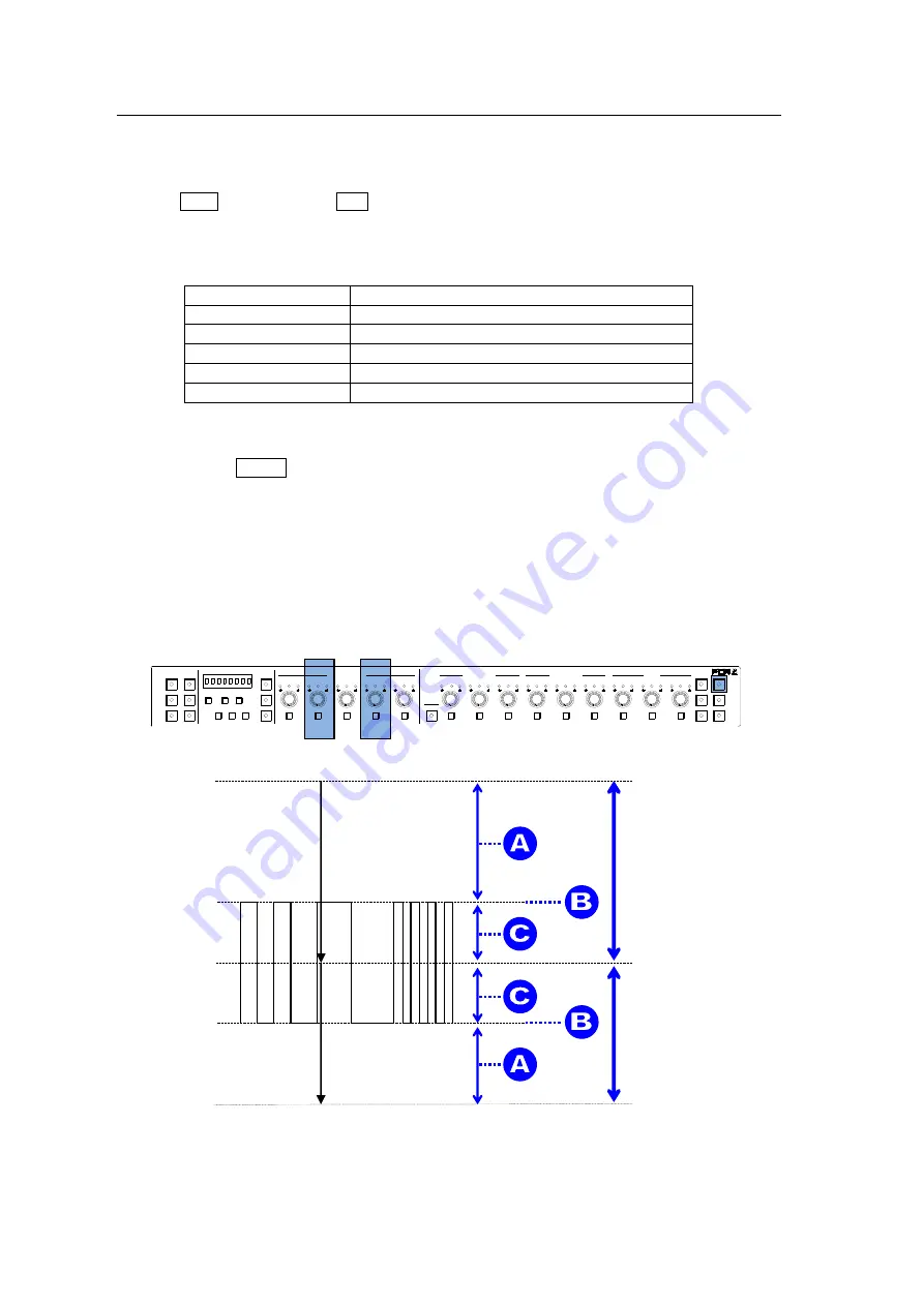
(3) Adjust the clip setting while viewing the three indicators above the controls and the value
on the MEMORY/SET display panel. (See
“Signal levels and level display” below.)
Pressing the UNITY button below the value resets the clip value to default.
(4) Repeat steps (2) and (3) to enter additional adjustments.
Signal levels and level display
The relationship between indicators, controls, and clip settings are as shown below.
RGB White Level and White Knee Point affect and interact with each other and change their
setting range accordingly. (RGB Black Level and Black Knee Point function in the same
manner.)
1-5
6-10
11-15/UNIT 16-20
BYPS/OP FS SEL
MEMORY/SET
0
1
2
3
4
5
6
7
FREEZE
CLIP
SPLIT
SELECT
-
+
SAVE LOAD CLEAR
PROCESS CONTROL
VIDEO LEVEL
Y LEVEL
C LEVEL
SETUP/BLUCK
HUE
UNITY
UNITY
UNITY
UNITY
UNITY
SYSTEM
GRP ADJ
UNITY
UNITY
UNITY
UNITY
UNITY
UNITY
R
G
B
R
G
B
WHITE LEVEL
BLACK LEVEL
UNITY
UNITY
UNITY
R
G
B
GAMMA
WHITE
BAL
FA-10DCCRU
CENTER
DIF
BLACK
SEPIA
150%
White Clip default value
100%
-50%
Black Clip default value
0%
50%
RGB Clip
Black Clip
setting range
White Clip
setting range


