background image

4.-

Speaker connection terminals. The output impedance is from 4 to 8 Ω. Connect the brown cable to the
terminal marked with + (speaker) and the white cable to the terminal marked with – (speaker).

CONNECTION

Connect the cables supplied in the screw terminals on the back panel of the amplifier. 

SPEAKER CONNECTION

Connect the output terminals to the speaker/speakers, the brown cable (+) to the positive terminal and the
white (-) to the negative terminal.
Make sure the connections are made correctly and that they are well insulated to avoid short circuits in the
speaker output which could damage the amplifier.
The speaker output accepts the connection of a charge impedance from 4 to 8 Ω. The speaker output
impedance is automatically adjusted to the charge, but the best results are achieved if the amplifier is charged
with 4 Ω.
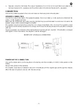
If various speakers are connected, the total impedance must be between 4 and 8 Ω. If the amplifier is charged
with higher or lower impedance, the amplifier could be damaged. 

EXAMPLE OF A PARALLEL CONNECTION

POWER SUPPLY CONNECTION

Connect the black cable (-) to the negative on the battery and the red cable (+12 V DC) to the positive on the
battery. 

Respect the polarity of the batteries.

The amplifier must only be installed in cars with 12 V batteries with the negative ground through the chassis.

When the fuse is replaced, use one with the same value.

- 5 -

EN

Содержание FS-75U

Страница 1: ...FS 75U AMPLIFIER WITH USB MP3 PLAYER AND SIREN EN Instruction manual...

Страница 2: ...llow ventilation Avoid direct sunlight heat sources and excessive dust Do not place the machine near magnetic elds or static electricity Do not use surfaces which vibrate or receive impact Do not pile...

Страница 3: ...product at no additional cost It also shows that the machine was put on the market after 13th August 2005 European Community Directive 2002 96 CE of Electrical and Electronic recycling and its Spanis...

Страница 4: ...on One long press switches between the NORMAL play mode the LED indicator for the USB MP3 player blinks slowly and RANDOM play mode the LED indicator blinks quickly 6 USB MP3 player volume control 7...

Страница 5: ...e the amplifier The speaker output accepts the connection of a charge impedance from 4 to 8 The speaker output impedance is automatically adjusted to the charge but the best results are achieved if th...

Страница 6: ...s between NORMAL play mode the LED indicator for the USB MP3 player will blink slowly and RANDOM play mode the LED indicator will blink quickly In both of these playing modes all the content is repeat...

Страница 7: ...c 6 3 mm mono jack 10 000 4 mV 1 auxiliary 6 3 mm stereo jack and 2 x RCA 10 000 100mV PRIORITY Mic and siren over USB MP3 player and auxiliary depending on signal level selectable VOLUME CONTROLS Mic...

Страница 8: ...ges burns spilt liquids or other substances excessive humidity battery deterioration and internal manipulation of the device the software or its components by unauthorized persons and in general any u...

Отзывы: