Follett Symphony 12CI400A Скачать руководство пользователя страница 10

10

Dispenser cleaning: start-up and quarterly intervals

1. Remove all ice from storage hopper.

2. Remove top and front cover (see page 30).

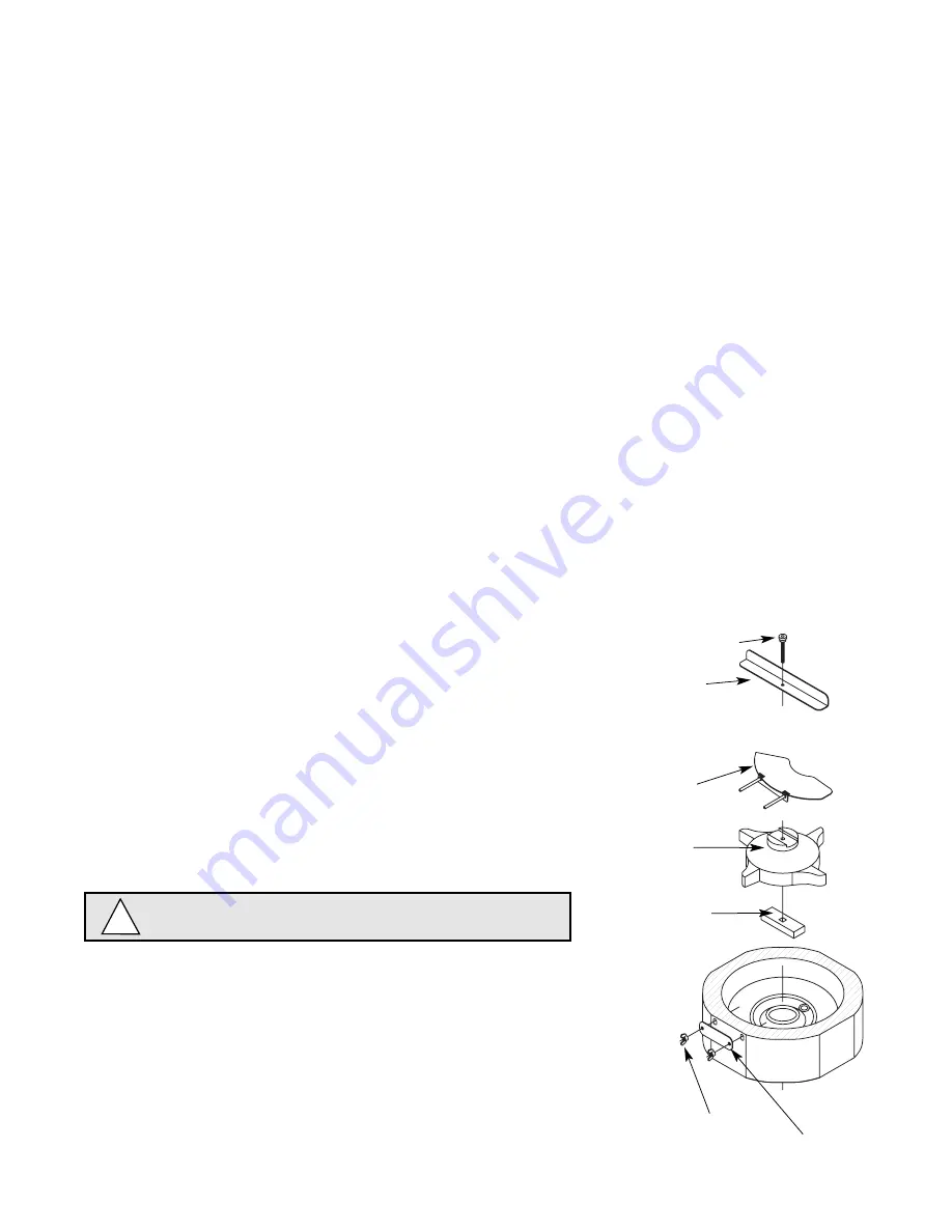
3. Remove center thumbscrew, locking plate, two wingnuts and

backing plate from front of storage hopper.

4. Remove stud assembly, agitator, spacer, baffle, wheel and drive

bar in this sequence.

User information

How the dispenser works

Follett’s 12 series automatic-load ice and water dispensers are equipped with Follett’s 400 lb (181kg)/day
icemaker. In the continuous icemaking process, water freezes to the inside wall of the evaporator. A rotating
stainless steel auger carries the ice to the top of the evaporator where it is compressed and extruded through an
outlet port. The ice is then pushed through a tube to the storage hopper. When the hopper is full, a bin thermostat
opens and shuts the icemaker off. When the dispense mechanism is activated, a dispense motor is turned on,
causing the wheel to turn. This moves ice to the dispense chute where it drops by gravity into the container held
below the chute.

How the SensorSAFE accessory works

Follett’s SensorSAFE accessory maximizes sanitation and minimizes the possibility of cross-contamination by
eliminating physical contact between the cup or container and dispenser. Sensors in the panel use reflected
infrared light to detect the presence of the container and send a signal to a control board which then activates the
appropriate components for ice or water dispensing. 

The SensorSAFE package includes a cleaning switch under the left side of the front cover which 
temporarily shuts off dispensing to allow cleaning of the panel and lenses. If the switch is not turned back  on after
cleaning, the dispenser automatically resets after two minutes for normal operation. 

SensorSAFE also includes a time limit safety feature which automatically stops ice dispensing after 
one minute of continuous dispensing. Dispensing can be resumed by moving the container away from 
the dispenser and returning it to the activation zone.

Cleaning and sanitizing procedures 

Solution A:

Prepare cleaning solution (200 ppm of available 
chlorine content) of Ecolab Mikro-chlor Cleaner or 
equal chlorinated detergent. Solution temperature 
must be 75

˚

F – 125

˚

F (24

˚

C – 52

˚

C).

Solution B:

Prepare sanitizing solution (50 ppm of available 
chlorine content) of Ecolab Mikro-chlor Cleaner or 
equal chlorinated detergent. Solution temperature must 
be 75

˚

F – 125

˚

F (24

˚

C – 52

˚

C).

Follett recommends the periodic cleaning schedule below to ensure the
quality of ice provided. Use only recommended cleaning solutions. Do
not use solvents, abrasive cleaners, metal scrapers or sharp objects. 

Warning – Always disconnect power before cleaning.

!

stud assembly

agitator

wheel

drive bar

baffle

backing
plate

wingnut

Содержание Symphony 12CI400A

Страница 1: ...accessory 12HI400A wall mount dispenser available with or without drain pan Following installation please forward this manual to the appropriate operations person 801 Church Lane PO Box D Easton PA 1...

Страница 2: ...lett equipment may be returned for credit under the following conditions 1 The equipment is new and unused 2 A return authorization number has been issued by customer service within 30 days after ship...

Страница 3: ...concealed shipping damage If damage is found notify the shipper immediately and contact Follett Corporation so that we can help in the filing of a claim if necessary Check your paperwork to determine...

Страница 4: ...0A Dispenser drain 3 4 FPT 3 4 FPT Water inlet 3 8 FPT 3 8 FPT Note Water shut off recommended within 10 feet 3m of dispenser Drain to be hard piped and insulated Maintain at least 1 4 per foot 20mm p...

Страница 5: ...out for connections through bottom 404mm 458mm 102mm 39mm 305mm 305mm 366mm 407mm 21mm 2 51mm 16 14 4 12 0 8 1 5 12 15 9 18 4 1 26mm Fig 1 Counter information 437 12mm diameter Installation Before you...

Страница 6: ...accidents Fig 2 Bottom exiting utilities countertop units Fig 4 bottom panel assembly 1 Carefully tip dispenser back to expose underside and block up in place 2 Screw legs shipped taped to drain pan o...

Страница 7: ...shown Fig 10 2 Mount support bracket to wall using fasteners of sufficient strength fasteners not included see Fig 6 3 Rough in water and drain lines Fig 10 4 Lift dispenser onto support bracket posi...

Страница 8: ...8 Fig 6 Wall mounting dimensions bottom of dispenser outline of dispenser Caution Do NOT rest dispenser weight on bottom of support bracket Fig 7 Wall mount side view 22 5 572mm 32 5 826mm 18 5 470mm...

Страница 9: ...water and drain tubing 407mm 77mm 3 254mm 3 5 3 77mm 1 25 32mm MAX 77mm 89mm 77mm MIN 0 88 23mm MIN 16 10 3 3 nut support bracket screw bottom panel 3 4 FPT drain 3 8 OD push in water inlet Fig 8 Wal...

Страница 10: ...panel use reflected infrared light to detect the presence of the container and send a signal to a control board which then activates the appropriate components for ice or water dispensing The SensorSA...

Страница 11: ...recommended below and more often if environmental conditions dictate Cleaning of the condenser can usually be performed by facility personnel Cleaning of the icemaker system in most cases should be p...

Страница 12: ...ace a large pan in bin storage area to catch ice or connect a separate ice transport tube to evaporator and divert ice into separate container 15 Fill reservoir almost to overflowing with sanitizing s...

Страница 13: ...ice is continuously removed by a slowly rotating 12 RPM auger The auger carries the ice upward into the cavity formed by the top bearing housing and the compression loop where it is compressed to rem...

Страница 14: ...ACK 33 41 1 4 UP COMPRESSOR RUN ORANGE 23 R BLACK S L BLACK WATER SOLENOID 32 S 30 4 1 C BLACK 4 1 28 BLACK 29 BLACK 25 21 RED COMPONENTS MOUNTED ON MAIN FRAME START S BLACK 22 1 M BLACK 2 FAN HIGH PR...

Страница 15: ...through the normally closed contacts of the bin thermostat and the bin signal switch When ice builds up around the bin thermostat the contacts open cutting the bin signal COMP START CAPACITOR COMP ST...

Страница 16: ...more than 10 seconds no reaction will occur GRD L1 L1 L2 L2 L2 L2 L2 COMPRESSOR FAN DRIVE DR C 20M 60M 2ND WTR B T B E RESET X GRD G B W FAN BLACK WHITE BLACK BLACK R ORANGE S S L COMPRESSOR C RED BLA...

Страница 17: ...1 COMPRESSOR SWITCH PWR BLACK T O L BLACK RED HIGH PRESSURE SAFETY SWITCH 4 2 3 RUN START T O L BLUE YELLOW BLACK WHITE M GRD L1 L1 L2 L2 L2 L2 L2 COMPRESSOR FAN DRIVE DR C 20M 60M 2ND WTR B T B E RES...

Страница 18: ...N DRIVE DR C 20M 60M 2ND WTR B T B E RESET X GRD G B W FAN BLACK WHITE BLACK BLACK R ORANGE S S L COMPRESSOR C RED BLACK BLACK WHITE INPUT POWER WATER SENSOR CONTROL BOARD BLACK GEARMOTOR 24V COMMON L...

Страница 19: ...IN T STAT BIN SIGNAL FROM DISPENSER JUNCTION BOX WHITE RED WHITE M 1 COMPRESSOR SWITCH PWR BLACK T O L BLACK RED HIGH PRESSURE SAFETY SWITCH 4 2 3 RUN START T O L BLUE YELLOW BLACK WHITE M GRD L1 L1 L...

Страница 20: ...N BOX WHITE RED WHITE M 1 COMPRESSOR SWITCH PWR BLACK T O L BLACK RED HIGH PRESSURE SAFETY SWITCH 4 2 3 RUN START T O L BLUE YELLOW BLACK WHITE M GRD L1 L1 L2 L2 L2 L2 L2 COMPRESSOR FAN DRIVE DR C 20M...

Страница 21: ...M Diagnostic sequence Stage 10 If the water level in the float reservoir drops to an unacceptable level the WTR LED goes out shutting the icemaker off Also the BT LED comes on preventing the icemaker...

Страница 22: ...er capacity 24 hrs Table 2 Compressor data Compressor current draw Air cooled Ambient air temp 60 F 15 6 C 70 F 21 1 C 80 F 26 7 C 90 F 32 2 C 100 F 37 8 C 6 3A 6 5A 6 7A 6 9A 7 1A Locked rotor amps 5...

Страница 23: ...reached close valves and both manifold and shut down the vacuum pump Allow the system to sit for approximately 20 minutes During this period the system pressure should not rise If the system pressure...

Страница 24: ...age hopper cover inside dispenser cabinet off or ajar Dispense switch contacts burned shut Faulty or incorrectly positioned bin stat 1 Faulty water solenoid valve 2 Faulty dispense switch 3 Power swit...

Страница 25: ...ontrol board replace board Problem Dispenses ice and or water continuously Board guide LEDs when illuminated indicate the following PWR board power CLN cleaning no dispensing cycle ICE ice dispensing...

Страница 26: ...7 Superheat incorrect 8 Inefficient compressor 1 O ring seal broken Corrective action 1 Check that unit is plugged in circuit breakers are on 2 Adjust or replace ice level control 3 Check reservoir f...

Страница 27: ...ss or binding and replace if necessary 5 Replace gearmotor start relay 6 Ensure that ice contacts bin thermostat before backing ice up in transport tube Refer to dispenser manual for proper thermostat...

Страница 28: ...sequence Wheelmotor removal 1 Remove dispense wheel and drive bar see above 2 Remove four 4 hopper support plate mounting screws and washers Fig 11 1 3 Move hopper assembly 1 2 13mm to left 4 Remove...

Страница 29: ...nozzle from evaporator port Evaporator reassembly 1 Clean gearmotor boss output shaft and shaft well 2 Install drain pan and evaporator mounting base 3 Fill gear motor shaft well with food grade grea...

Страница 30: ...unit and pull fan assembly toward front of unit c As fan assembly is being pulled toward front rotate assembly clockwise as shown above Fan removal Side panels Remove screw located on lower rear side...

Страница 31: ...t Ice transport tube tube may extend a maximum of 1 4 6mm into ice bin Top view 25 ice tube gasket ice tube retainer 50 TYP 3 76mm capillary tube bracket Ice transport tube replacement 1 Push tube ont...

Страница 32: ...ing water inlet brass Not shown 502924 Fitting water inlet plastic Not shown 00137315 Fitting water inlet brass 3 8 FPT 9 502884 Lid top panel plastic 10 502396 Panel right side 11 502395 Panel left s...

Страница 33: ...pillary tube See page 31 502404 Retainer ice tube 2 high See page 31 00152017 Retainer ice tube 2 25 high See page 31 502405 Gasket ice tube See page 31 502413 Assembly hopper includes drain fitting 1...

Страница 34: ...over the dispense button 7 502057 Fastener dispense chute assembly 8 501250 Screws dispense lever 9 502427 O ring 10 502561 Fitting 1 4 tube 11 502562 Fitting 3 8 tube 12 502419 Support bracket soleno...

Страница 35: ...502819 Cover dispense chute 6 502421 Solenoid assembly includes solenoid fittings tube mounting bracket 7 see page 34 for exploded view 502690 Lens sensor 8 203611 Ty rap sensor mounting 9 502675 Spla...

Страница 36: ...polypropylene reservoir supply sold by the foot 19 502383 Bracket float valve 20 502403 Tube ice transport 21 501176 Insulation ice tube 12 305mm required 22 307192 Bracket gearmotor mounting 23 5027...

Страница 37: ...6 27 25 22 23 24 21 20 19 17 2 13 14 12 15 16 29 7 8 6 5 10 1 PANELS REMOVED CAUTION HAZARDOUS MOVING OPERATE UNIT WITH PARTS DO NOT PANELS REMOVED OPERATE UNIT WITH 9 29 29 Rear view Right side view...

Страница 38: ...Board control circuit 115V 60Hz 3 502116 Water sensor 4 502392 Switch on off compressor 5 502209 Switch rocker power 6 502209 Switch rocker bin signal 7 502409 Switch cleaning SensorSAFE models 8 502...

Страница 39: ...ndensate 9 501080 Screw Allen 1 4 20 x 1 2 set of 4 10 502733 Mounting base evap includes 501063 11 502227 Bolt mounting base 12 00142034 Gearbox motor includes 307192 13 502729 Mounting base gearbox...

Страница 40: ...208595R09 09 06 801 Church Lane PO Box D Easton PA 18044 USA Toll free 800 523 9361 610 252 7301 Fax 610 250 0696 www follettice com...

Отзывы: