


DISPENSER
Left junction box
GND
GRN
B
W
Right junction box
BL
Y
RD
W
B
Lower junction box
(24V bin signal)
Ice machine #2
(optional)
W
B
X
GND
GRN
B
W
Lower junction box
(24V bin signal)
Ice machine #1
(optional)
Upper junction box
(power)
X
GND
GRN
B
W
Upper junction box
(power)
LEGEND
X
EQUIPMENT
GROUND
WIRENUT FIELD
CONNECTIONS
B
BLACK
W
WHITE
GRN
GREEN
BL
BLUE
Y
YELLOW
RD
RED
X
GND
GRN
W
B
W
R
Lower ice machine
junction box
(bin signal)
B
Dispenser
junction box
X
W
GND GRN
Upper ice machine
junction box
(power)
B
Electric
power
source
Electric
power
source
Electric
power
source
Electric
power
source
Electric
power
source
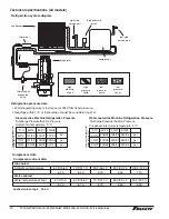
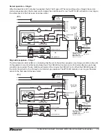
Recommended junction box preparation of hard-wired RIDE
model ice machines.
1. Cut plugs from supplied power cords.
2. Replace upper (power) strain relief with
a cord connector.
3. Mount two 2" x 4" junction boxes using supplied holes in
ice machine face.
4. Make power and bin signal connections.
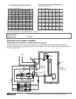
Field wiring diagrams for RIDE model ice machine installations
§
All field wiring must be installed in accordance with NEC and local electrical codes.
§
Field wiring diagram is intended only to aid electrician or technician in understanding how equipment works.
§
Should local codes require a hard-wired connection and/or shielded wiring, eliminate the cord and plug(s) and
follow the appropriate field wiring diagram.
§
MCD400A/W and R400A/W ice machines have separate power supply from dispenser.
§
Electric disconnects required within 10 ft (3 m) for all hard-wired connections.
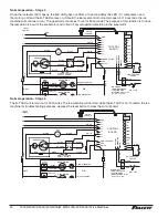
25, 50 or 110 ice and water dispenser with ONE RIDE model ice machine
(dispenser models 25CR400A/W, 25HR400A/W, 50CR400A/W, 50HR400A/W, 110CR400A/W)
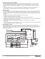
VU155/VU300 ice and beverage dispenser with ONE or TWO RIDE model ice machines
Note: 24 V bin signal; Verify black bin signal wire is on the 24 V terminal
10
T400A/W, MCD400A/W, R400A/W, MFD400A/W, D400A/W Ice Machines


