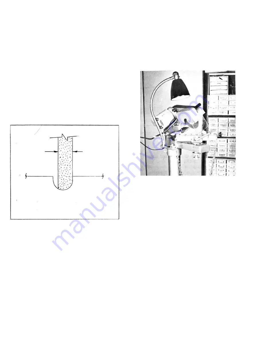
DRESSING THE GRINDING WHEEL
1. Shape the wheel "freehand" by holding the dresser
against the wheel while it is running. Use a circular
motion to produce the desired curvature on the
wheel.
2. Stop the motor and check the wheel shape with the
radius gauge.
3. The chart on page 7 shows the recommended
wheel thickness for different chains.
A narrower wheel may be used instead of the one
recommended in the chart, if it is dressed as shown
in Fig. No. 3. For example, if the chart calls for a
1/4
"
thick wheel, a 3/16" thick wheel can be dressed
to fit one side of the 1/4
"
gauge. This will be helpful
on certain chains where the thicker wheel may in-
terfere with the depth gauges.
Illustration No. 3
GRINDING CHIPPER CHAIN
1. Choose and dress the grinding wheel as explained
above. Refer to Fig. No. 6 for correctly ground chip-
per cutter.
2. Lay the chain in the vise with the cutting edges fac-
ing to the left.
3. Tilt the grinding head to 30° and lock.
4. Set and lock the chain vise at 35° to the left (rotat-
ing clockwise from 0°). See Illustration No. 4.
5. Set chain vise to 0° on the horizontal scale and lock
in place.
6. Position the stop finger behind the right hand cutter
to be ground and align the tooth to the grinding
wheel. Set the depth stop.
7. Turn motor switch to "Forward" position (counter-
clockwise rotation when viewed from wheel end of
shaft) and adjust the stop finger to give the lightest
grinding pass that will sharpen the tooth properly.
Grind all right hand cutters in the chain without
changing your set up.
Illustration No. 4
Page 4
8. Swing chain vise to the right and lock at 35°. See
Illustration No. 5.
9. Position stop finger behind a left hand cutter and
align the tooth to the grinding wheel. Change only
stop finger position if necessary.
10. Grind all left hand cutters with the motor switch in
the "Reverse" position.
11. After sharpening the chain and before removing
it from the grinder check the depth gauge by lay-
ing a short straight edge across the top of two
cutters then using a feeler gauge to measure the
distance between top of depth gauge and bottom
of straight edge. Proper depth gauge setting is
shown on chart page 7... Depth gauges can also
be checked by using #370362 Oregon Adjustable
Depth Gauge.
If depth gauges need to be lowered, use a 5/16" thick
grinding wheel. Dress the wheel to match the contour
of the depth gauges (See Illustration No. 7). Set the
grinding head to 0° and to 0° on both the chain vise
scale and the horizontal scale. Set the depth control to
give proper height and grind all depth gauges.
3/16 WHEEL
1/4 GAUGE
Содержание 308
Страница 3: ......
Страница 4: ......
Страница 13: ......
Страница 15: ...394930 PEDESTAL ...
Страница 17: ......


