22
B 540-27-F + feed pump_7009077
US – 07-02-2019
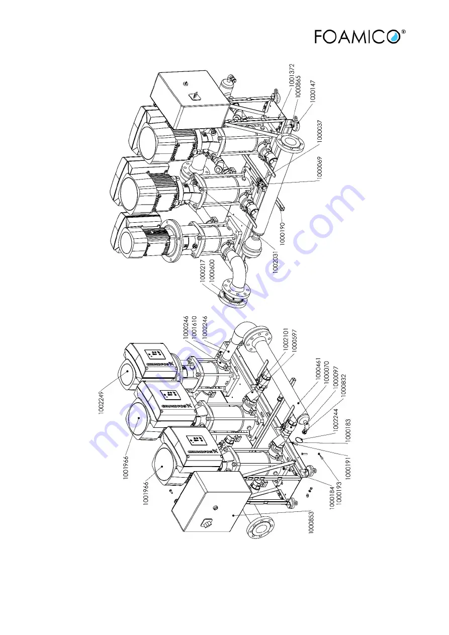
Figure 8.1 Booster
Страница 1: ...1B 540 27 F feed pump_7009077 US 07 02 2019 Manual FOAMICO Booster Station B 540 27 F Feed pump 7009077...
Страница 2: ...cation and Mounting 10 3 3 Water Supply 10 3 4 Electrical Supply 11 4 Operation 12 4 1 Start procedure 12 4 2 Stop procedure 13 5 Troubleshooting 15 5 1 Failures control system 15 5 2 The pump does no...
Страница 3: ...ble return from FOAMICO after finished repairs rest with FOAMICO The defect parts are the property of FOAMICO Claims which might be raised for any other legal reason or normal wear and tear as well as...
Страница 4: ...the person responsible for this product Should the manual get lost please don t hesitate to require another one from your agent 1 5 Declaration of conformity We FOAMICO declare that this product is i...
Страница 5: ...the product or something in its vicinity could be damaged Prevention 2 Safety 2 1 Safety during operation of the system WARNING Burn hazard The operating machine presents a danger of scalding from ho...
Страница 6: ...injuries ear damage danger of swallowing loss of stability Directing a jet of water cleaning fluid or liquid disinfectant at persons can lead to eye injury or ear damage swallowing or the loss of sta...
Страница 7: ...by the impact from the water jet on the surroundings It is therefore recommended the use ear protectors during the cleaning process NOTICE The hand arm vibration level measured by using a low pressure...
Страница 8: ...OAMICO low pressure system is manufactured with the purpose of Rinsing with water spreading foam and sanitizer within the stated boundaries Any other kind of application or use beyond this is consider...
Страница 9: ...ructions for Mounting and Installation CAUTION Personal injury and damage to property may result from the installation of damaged parts The installation of damaged parts may cause personal injury and...
Страница 10: ...distance from the water supply the maximum water flow and vertical distance from the boosting System 3 3 Water Supply NOTICE Connection to water supply should always be done in according to local or n...
Страница 11: ...rk on the electric equipment of the main station can result in severe injury and death The user or the installer is responsible for the installation of correct earthing and protection according to cur...
Страница 12: ...illed the pump and other components may be damaged Do not start the main station until the pipe system has been filled with water and vented Do not start the main station until the pump has been fille...
Страница 13: ...switch shall always be turn off STOP Turn the On Off switch POS C Fig 4 1 into position Off The booster station is now stopped Read the section on Operating mode in the Grundfos manual Grundfos Hydro...
Страница 14: ...7 bar Inlet pressure Actual measured inlet pressure Liquid temp water temperature in top of the pump Figure 4 3 Display photo Pump running Discharge press Stop Actual discharge pressure from pump maxi...
Страница 15: ...he water level in the tank is below minimum Fill the tank The ball valve at the inlet of the system is not opened Open the ball valve Unstable rinsing pressure Unoriginal rinsing nozzle with too high...
Страница 16: ...ollowing Check for water leakages in the pipe system Check the non return valve Check the flow switch Reset the unit Turn the Switch POS C fig 4 1 into 0 position for 5 seconds Turn the Switch POS C f...
Страница 17: ...s Reset the unit Turn the Switch POS C fig 4 1 into 0 position for 5 seconds The unit will start when there is water consumption Follow the instruction at the display to set it back to the home screen...
Страница 18: ...security reasons it is recommended to change the hose at least once every 12 months 6 2 Nozzles Nozzles are warned over time And warned out nozzle is less effective It can result in less rinsing powe...
Страница 19: ...s own air supply system Failure in the cleaning system could accidentally lead to water and or detergent can flow back in the air system To avoid damage on other installations It is mandatory to make...
Страница 20: ...43 3A Fuse A 63 Dimension W x H x D mm 1645 x 1070 x 905 Weight kg 450 All Measurements are average 7 1 Resulting outlet pressure The pump is programmed to deliver the maximum possible outlet pressure...
Страница 21: ...21 B 540 27 F feed pump_7009077 US 07 02 2019 8 Spare parts 8 1 Booster B 540 27 F Feed pump All Measurements are average...
Страница 22: ...22 B 540 27 F feed pump_7009077 US 07 02 2019 Figure 8 1 Booster...
Страница 23: ...23 B 540 27 F feed pump_7009077 US 07 02 2019 Table 8 1 Booster station B540 27 F Feed pump 9 Wiring diagram The electrical diagram is delivered as a separate part of the manuals...
Страница 24: ...4 B 540 27 F feed pump_7009077 US 07 02 2019 9 1 Flow Diagram In and outlets A Water inlet A Water inlet Components 2 Ball valve 2 Ball valve 4 Pump 4 Pump 7 Pressure transmitter 7 Pressure transmitte...
Страница 25: ...2019 10 Name Plate 1 Company Name 8 Maximum pressure 2 Production date 9 Min Max inlet pressure 3 Serial number 10 Power 4 Item Number 11 Current 5 Model type 12 Voltage 6 Maximum allowed flow 13 Fre...
Страница 26: ...F B 050 27 C B 065 27 F B 065 27 C B 100 27 F B 100 27 C B 120 27 F B 120 27 C B 200 27 F B 200 27 C B 270 27 F B 270 27 C B400 F B540 F B630 F B630 F B810 F B1080 F B540 F Feed pump to which this dec...