background image

Operation Manual RTM MP System 


06.09.2017


21 


5.4


Calibration Methods 

The Calibrating procedure (setting 
the Gain), adjusts the controller 
and force sensors so that the 
output gives you the actual tension 
value. There are two methods of 
calibrating the system. The first 
method uses a defined weight. The 
second method is based on a 
calculation method in conjunction 
with the FMS Calculator. This 
Calculator can be down loaded 
from the FMS web page. FMS 
recommends using the method 
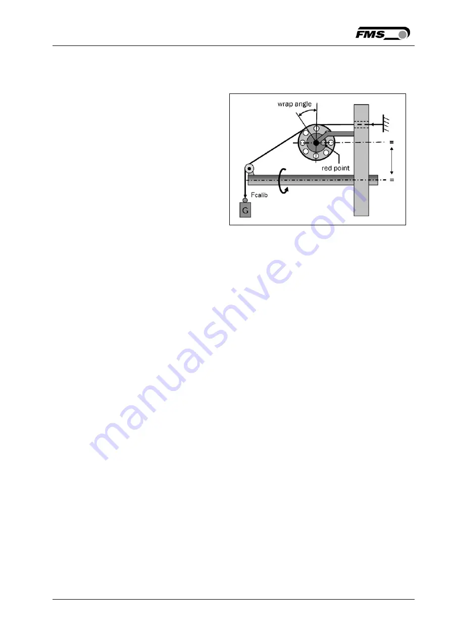
with the weight (see Fig. 13) since 
it delivers the most accurate 
results. 


5.5


Calibration Procedure 

1.


The calibration of the sensors must be performed with the PLC 

2.


Load a rope on the roller with the weight corresponding to your calibration force. 
The roller configuration must correspond to the real material path in the machine 
(wrap angle, distances between the rollers etc.). 

3.


The RTM MP-system will deliver tension raw data via the corresponding output 

4.


Enter the force data in your PLC and calibrate it matching your controlling needs. 


5.6


Relay Output for Lost Communication 

The relay output on the receiver EMGZ482R.MP becomes active, if the 
communication link between receiver and transmitter is lost. For the technical 
specification of the relay output see chapter 8 “Technical Data”, Table 
EMGZ482R.MP. 


Fig. 13: Calibrating the measuring amplifier    
 

RTM00020e 

Содержание RTM MP EMGZ443MP.R

Страница 1: ...der Signal Evaluation Version 3 07 12 2014 ff Firmware Version V 3 03 This operation manual is also available in German Please contact your local FMS representative Diese Bedienungsanleitung ist auch in Deutsch erhältlich Bitte kontaktieren Sie Ihren nächstgelegenen FMS Vertreter by FMS Force Measuring Systems AG CH 8154 Oberglatt All rights reserved ...

Страница 2: ...iring the Electronic Components 10 4 5 Mounting and Wiring the Transmitter EMGZ482T MP 24VDC 11 4 6 Components on the Static Part of the Machine 12 4 7 Wiring the Receiver EMGZ482R MP 13 4 8 In and Output Schematics EMGZ443MP T and R 14 4 9 Connectors EMGZ443MP T rotating machine part 15 4 10 Connectors EMGZ443 MP R static machine part 17 5 Configuration of the RTM MP System 19 5 1 RTM MP Quick St...

Страница 3: ...n limits neither during assembly nor operation To do so can be potentially harmful to persons or equipment in the event of a fault to the equipment 1 1 Description conditions a Danger of health injury or loss of life Danger This symbol refers to high risk for persons to get health injury or loss life It has to be followed strictly b Risk of damage of machines Caution This symbol refers to informat...

Страница 4: ...o located or operating in conjunction with any other antenna or transmitter It is of paramount importance to compensate the centrifugal forces caused by the rotating base plate of the stranding machine The measuring results will be wrong if this rule is broken Proper function of the FMS RTM MP System can only be guaranteed with the recommended application of the components Other arrangements can c...

Страница 5: ...y of analogue and digital I Os and thus create the multi channel multi purpose system RTM MP The expansion module EMGZ443MP T is used in the transmitter side rotating part of the machine The EMGZ443MP R expands the system on the receiver side static part of the machine A fully expanded system can handle 2 force measuring rollers 4 Encoders 2 analogue I Os and 16 digital I Os In addition a relay co...

Страница 6: ...Z482R MP Wireless reception of tension data Offset compensation Bus connection to EMGZ443MP R Data transfer to EMGZ443MP R and PLC EMGZ443MP T Extension Module Multi Purpose Transmitter Side Expansion of I O Configuration by 1x Analogue output 0 10V or 4 20mA 1x Analogue input 0 10V or 4 20mA 2x Encoder Inputs 8x Dig outputs 8x Dig inputs EMGZ443MP R Extension Module Multi Purpose Receiver Side Ex...

Страница 7: ... device pursuant to Part 15 of the FCC Rules Certification FCC Registration 0020311882 Note This equipment has been tested and found to comply with the limits for a Class A digital device pursuant to Part 15 of the FCC Rules These limits are designed to provide reasonable protection against harmful interference when the equipment is operated in a commercial environment This equipment generates use...

Страница 8: ... two conditions 1 this device may not cause harmful interference and 2 this device must accept any interference received including interference that may cause undesired operation Caution Radiofrequency radiation exposure Information This equipment complies with FCC radiation exposure limits set forth for an uncontrolled environment This equipment should be installed and operated with minimum dista...

Страница 9: ... of the sensor The installation manual is always delivered together with the sensor 4 3 Force Measuring Sensors on a Rotating Machine Part Note In rotating applications the force measuring sensors are mounted such that centrifugal forces are compensated If using FMS RMGZ sensors this can be achieved by turning the Red Point parallel to the rotation axis and in direction of the positive force compo...

Страница 10: ... is usually delivered complete with all its components and cables The cables are prepared with connectors on both sides for easy assembly Caution Proper function of the FMS RTM MP System can only be guaranteed with the recommended application of the components Other arrangements can cause malfunctions Therefore the installation instructions on the following pages must be followed Caution Local ins...

Страница 11: ...T MP 24VDC transmitter close to the RMGZ load cells to keep the signal cables short If no standard FMS cables are used the connection between force sensors and transmitter must be wired with 2x2x0 25mm2 AWG 23 shielded twisted pair cable The wiring diagram below Fig 4 shows how the signals are wired to the connectors Fig 4 Signal assignment EMGZ482T MP RTM MP007e Connectors are shown from the mati...

Страница 12: ...ck to persons malfunction of the total system or damage of the electronic unit It is vital to ensure that proper earth connection is done Caution The sensor cables must be installed separate from power lines 4 6 Components on the Static Part of the Machine Following RTM MP components are installed on the static part of the system Receiver EMGZ482R MP Multi purpose extension module EMGZ443MP R Cabl...

Страница 13: ...r EMGZ482R MP EMGZ482R MP receives the data captured by the RTM transmitter and acts as an interface to a PLC or to a close loop tension controller Fig 6 shows the pin assignment on the electronic board Fig 6 Signal assignment EMGZ482R MP on electronic board RTM MP008e ...

Страница 14: ...Operation Manual RTM MP System 06 09 2017 14 4 8 In and Output Schematics EMGZ443MP T and R Fig 7 In Output configuration EMGZ443MP T and R RTM MP0011e ...

Страница 15: ...Operation Manual RTM MP System 06 09 2017 15 4 9 Connectors EMGZ443MP T rotating machine part Fig 8 Signal assignment EMGZ443MP T 1st part RTM MP 003e Connectors are shown form the mating side ...

Страница 16: ...Operation Manual RTM MP System 06 09 2017 16 Fig 9 Signal assignment EMGZ443MP T 2nd part RTM MP 004e Connectors are shown form the mating side ...

Страница 17: ...Operation Manual RTM MP System 06 09 2017 17 4 10 Connectors EMGZ443MP R static machine part Fig 10 Signal assignment EMGZ443MP R 1st part RTM MP005e Connectors are shown form the mating side ...

Страница 18: ...Operation Manual RTM MP System 06 09 2017 18 Fig 11 Signal assignment EMGZ443MP R 2nd part RTM MP006e Connectors are shown form the mating side ...

Страница 19: ...ransmitter EMGZ482T MP and receiver EMGZ482R MP 2 The RTM MP system will establish the wireless radio link automatically This initial process can take 5 10 sec 3 After having achieved a stable radio link the LCD display on the EMGZ482R MP will show 4 The system is now ready to be calibrated 5 2 Description of the Operating Panel EMGZ482R MP Fig 12 View of the Operating Panel EMGZ482R MP RTM MP 009...

Страница 20: ...Offset Compensation one can compensate the roller weight of the sensor This procedure is always performed before the calibration The roller weight compensation is performed for both channels sensor 1 and sensor 2 The force measuring roller should not be loaded while the Offset Compensation is being done Procedure 1 Remove any wires that may apply a force to the roller 2 Close a contact between ter...

Страница 21: ...ocedure 1 The calibration of the sensors must be performed with the PLC 2 Load a rope on the roller with the weight corresponding to your calibration force The roller configuration must correspond to the real material path in the machine wrap angle distances between the rollers etc 3 The RTM MP system will deliver tension raw data via the corresponding output 4 Enter the force data in your PLC and...

Страница 22: ...Operation Manual RTM MP System 06 09 2017 22 6 Mechanical Dimensions Fig 14 Dimensions EMGZ482T MP 24VDC RTMX2 0020US Fig 15 Dimensions EMGZ482R MP RTX2 0018US ...

Страница 23: ...nual RTM MP System 06 09 2017 23 The EMGZ443MP T and EMGZ443MP T differ in their connector assignment The mechanical dimensions of the housing are the same Fig 16 Outline Drawing EMGZ443MP T and EMGZ443MP R E443001 ...

Страница 24: ... 3 Periodic oscillation on wire tension reading Sheave weight influences the measurement or Alignment of red point is incorrect Perform Offset compensation see chapter 5 3 or See chapter 4 2 and 4 3 Align red point correspondingly and re calibrate the system chapters 5 4 and 5 5 Feedback value doesn t correspond to the effective material tension Alignment of red point is incorrect See chapter 4 2 ...

Страница 25: ...1 sensor with strain gauges 350 Ω 0 5 4 mV max 7 4 mV Temperature Range 0 50 C 32 122 F Protection Class IP52 Weight 0 52 kg 1 15 lbs EMGZ482R MP Number of Channel 2 channels Displays LCD 2x 8 characters 8mm Supply voltage indicator Propagation delay 5ms Resolution D A Converter 0 4096 12 Bit Wireless Interface 2 44 GHz Analogue Output 1 0 10 VDC min 1 2kΩ or 4 20mA max 500Ω Analogue Output 2 0 10...

Страница 26: ... 15 30 VDC max 2 W Power consumption max 10W Temperature range 0 50 C 32 122 F Protection class IP52 Weight 0 6 kg 1 32 lbs EMGZ443MP R Propagation delay 5 ms Interface RS485 Proprietary Analogue output 0 10 VDC or 4 20mA Analogue input 0 10 VDC or 4 20mA Encoder inputs 2 channels max 100kHz Digital outputs 8 outputs max 100 mA output source Digital inputs 8 inputs 5 36 VDC Power supply 24VDC 18 3...

Страница 27: ...Operation Manual RTM MP System 06 09 2017 27 ...

Страница 28: ...ogy com FMS Italy Via Baranzate 67 I 20026 Novate Milanese Tel 39 02 39487035 Fax 39 02 39487035 fmsit fms technology com FMS USA Inc 2155 Stonington Ave Suite 119 Hoffman Estates IL 60169 USA Tel 1 847 519 4400 Fax 1 847 519 4401 fmsusa fms technology com FMS UK Highfield Atch Lench Road Church Lench Evesham WR11 4UG Great Britain Tel 44 1386 871023 Fax 44 1386 871021 fmsuk fms technology com ...

Отзывы: