background image

Operating Manual EMGZ470A/472A 


2


Definitions 

Offset:

 Correction value for compensation of the zero point difference. The offset 

adjustment ensured that a force of 0N will generate a signal of 0V exactly. 
 

Gain:

 Amplification factor for the measuring signal. Use of proper value will set the 

measuring range of the sensor exactly corresponding to the signal output range. 
 

Strain gauge:

 Electronic component that changes its resistance when it is extended. 

Strain gauges are used in the FMS force sensors to gather the feedback value.


3


System Components 

The EMGZ470A.W/472A.W consists of the following components (refer also to fig. 
1): 

Force sensors 


For mechanical/electrical conversion of the tension force 


Force measuring bearing 


Force measuring roller


Force measuring journal


Force measuring bearing block


Electronic unit EMGZ470A.W/472A.W 


EMGZ470A.W: For supplying one force sensor and amplifying the mV signal 


EMGZ472A.W: For supplying two force sensors and amplifying the mV signal 


EMGZ470A.W.D.W/472A.D.W: For supplying one or two double range force 
sensors and amplifying the mV signals 


With intergrated PROFIBUS interface for operation and parametrization 


Operates as PROFIBUS DP slave according to EN 50170 


For wall mounting, set off of force sensor (EMGZ470A.W.W)


PROFIBUS master computer 


For operation of the electronic unit EMGZ470A.W/472AW 


Operates as PROFIBUS DP master according to EN 50170 


Any master computer or PLC suitable 


(Italic text indicates a variant or an option)


Содержание EMGZ470A.W

Страница 1: ...ing Manual Version 2 3 04 2007 ff Firmware Version from 1 04 08 2006 GSD Version 1 03 05 02 This operating manual is also available in German Please contact your local representative Diese Bedienungsanleitung ist auch in Deutsch erhältlich Bitte kontaktieren Sie Ihren nächstgelegenen FMS Vertreter by FMS Force Measuring Systems AG CH 8154 Oberglatt All rights reserved ...

Страница 2: ...s only guaranteed if the application and component recommendations are followed In case of other arrangement heavy malfunction can be the result Therefore the installation instructions on the following pages must strictly be followed Local installation regulations are to preserve safety of electric equipment They are not taken into consideration by this operating manual However they have to be str...

Страница 3: ...suring Amplifier 10 7 3 Wiring from Measuring Amplifier to Force Sensor 10 7 4 Wiring of Power Supply and PROFIBUS Data Cable 11 7 5 Wiring Diagram 12 7 6 Setting the PROFIBUS Address 13 8 PROFIBUS Interface Description 14 8 1 GSD File 14 8 2 EMGZ470A W 472A W DP Slave Functional Description 14 8 3 Initial Parameters 14 8 4 Configuration 15 8 5 Process Data 16 9 Calibrating the Measuring Amplifier...

Страница 4: ...ors For mechanical electrical conversion of the tension force Force measuring bearing Force measuring roller Force measuring journal Force measuring bearing block Electronic unit EMGZ470A W 472A W EMGZ470A W For supplying one force sensor and amplifying the mV signal EMGZ472A W For supplying two force sensors and amplifying the mV signal EMGZ470A W D W 472A D W For supplying one or two double rang...

Страница 5: ...ansmitted to the electronic unit as mV signal Power supply exerts influence to the strain gauges Wheatstone Bridge The force sensors are therefore supplied from the electronic unit with a very accurate power supply 4 3 Electronic Unit EMGZ470A W 472A W Common The electronic unit contains a microprocessor to handle all calculations and communications the highly accurate sensor power supply and the ...

Страница 6: ... to 10V This signal will be fed to the A D converter The microprocessor then calculates a standardized signal from the digitized measuring value which is fed to the PROFIBUS interface PROFIBUS interface The EMGZ470A W 472A W operates as PROFIBUS DP slave according to EN 50170 All settings and the entire communication is done by the integrated PROFIBUS interface 4 4 Block Diagram fig 2 E470002e ...

Страница 7: ...ents refer to 7 Installation and wiring Make settings in the PROFIBUS master computer DP master ref to 8 PROFIBUS Interface Description Put measuring amplifier into operation and calibrate it by PROFIBUS refer to 9 Calibrating the measuring amplifier Turn system on proceed with a test run with low speed If required activate additional application specific functions of the PROFIBUS master computer ...

Страница 8: ...Operating Manual EMGZ470A 472A 8 6 Dimensions 6 1 Dimensions of Offset Version EMGZ470A W fig 4 Outline drawing EMGZ470A W 472A W E470004us ...

Страница 9: ...Operating Manual EMGZ470A 472A 9 6 2 Dimensions Double Channel Version EMGZ470 472A W D fig 5 Outline drawing EMGZ470 D W 472 D W E472001e ...

Страница 10: ...ver they have to be strictly followed 7 1 Mounting the Force Sensors Mounting of the force sensors is done referring to the FMS installation manual which is delivered together with the force sensors 7 2 Mounting of the Measuring Amplifier The measuring amplifier is mounted directly to the force sensor using the FMS standard plug fig 3 When using the offset version EMGZ470A W EMGZ472A W the housing...

Страница 11: ...ck to persons malfunction of the total system or damage of the measuring amplifier It is vital to ensure a good earth ground connection Caution Improper handling of the amplifier unit may damage the fragile electronic circuitry Don t use rough tools such as screwdrivers or pliers Handling in the electronic unit must always take place with the operator using well earthed antistatic bracelets This w...

Страница 12: ... connected Bus in both termination jumpers have to be set fig 8 and 9 Note The PROFIBUS network has to be terminated properly Otherwise the installation cannot be put into operation Please ensured that only the last device of the PROFIBUS chain is terminated 7 5 Wiring Diagram fig 8 Wiring diagram EMGZ470A W 472A W E470006e fig 9 Wiring diagram EMGZ470A W D 472A D E472002e ...

Страница 13: ... 0011 1001 82 0101 0010 107 0110 1011 8 0000 1000 33 0010 0001 58 0011 1010 83 0101 0011 108 0110 1100 9 0000 1001 34 0010 0010 59 0011 1011 84 0101 0100 109 0110 1101 10 0000 1010 35 0010 0011 60 0011 1100 85 0101 0101 110 0110 1110 11 0000 1011 36 0010 0100 61 0011 1101 86 0101 0110 111 0110 1111 12 0000 1100 37 0010 0101 62 0011 1110 87 0101 0111 112 0111 0000 13 0000 1101 38 0010 0110 63 0011 ...

Страница 14: ...MGZ470A W 472A W DP Slave Functional Description The measuring amplifier EMGZ470A W 472A supports the PROFIBUS DP protocol according to EN 50170 Hereby the measuring amplifier operates as DP slave and the control system as DP master Several parameters have to be set and met by the control system 8 3 Initial Parameters Initialisation parameters are sent from the control system to the measuring ampl...

Страница 15: ...legram Slave Master Status Byte Status Main feedback value Higher Byte Main feedback value Lower Byte Module 2 Feedback value with status The control system sends periodically an empty telegram The measuring amplifier answers with the actual feedback value and with a status byte which indicates the quality of the feedback value This configuration can be used after offset and gain adjustment has be...

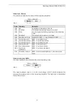
Страница 16: ...SW User Offset to be written 25h Find User Offset Measuring value will be set to zero 29h Read User Gain 2Bh Write User Gain HSW User Gain to be written 2Dh Calibrate User Gain HSW Force value which corresponds to the actual material tension F9h Read Firmware Version Main reference value HSW The main reference value transmits the actual parameter value Module 1 only Master Slave STB HSW Bit 15 0 T...

Страница 17: ...IW 2 21h User Offset read HIW User Offset read 23h User Offset written HIW User Offset written 25h User Offset found HIW User Offset found 29h User Gain read HIW User Gain read 2Bh User Gain written HIW User Gain written 2Dh User Gain calibrated HIW User Gain calculated F9h Firmware Version HIW main version high byte sub version low byte Main actual value HIW The main feedback value transmits the ...

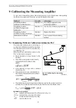
Страница 18: ... calibration inside the machine The material tension will be simulated by a weight fig 10 Offset and Gain calibration is done in the PLC or the master computer Insert material or a rope loosely to the machine The offset corresponds to the actually transmitted main feedback value HIW HIW offset Load material or rope with a defined weight fig 10 The gain factor is now calculated from the actually tr...

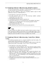
Страница 19: ...nal load We recommend to set Offset and Gain so that loading the sensor at nominal force will give a feedback value of 10000 9 3 Simulating Method Calibration using Control Byte Module 1 only The following instructions refer to a setup and calibration inside the machine The material tension will be simulated by a weight fig 10 Offset and Gain calibration is done in the measuring amplifier using th...

Страница 20: ...ed by the following formula Definition of symbols α angle between vertical and measuring web axis FB material tension β angle between vertical and FM FG roller weight γ wrap angle of material FM measuring force resulting from FB γ1 entry angle of material FMef f effective measuring force γ2 exit angle of material n number of force sensors δ Angle between measuring web axis and FM Enter control byt...

Страница 21: ...ass filter is configured by setting the cut off frequency and its filter order You determine the setting value in the table below and send it to the measuring amplifier using the initial parameters byte 3 ref to 8 3 Initial parameters Lowpass filter cut off frequency Setting value for filter of 1st order Setting value for filter of 2nd order Filter OFF 00h 00h 1 Hz 43h C3h 2 Hz 44h C4h 5 Hz 45h C5...

Страница 22: ...t correspond with the effective material tension Gain badly calculated Proceed for measuring amplifier calibration again refer to 8 6 Calibrating the Measuring amplifier does not respond by PROFIBUS red LED DIP switch and station address setting in the PROFIBUS DP master don t match Verify correct DIP switch and station address lights Application in PLC master computer reads from a wrong I O addre...

Страница 23: ... FS Cycle time 2ms Operation entirely by PROFIBUS Feedback value integer 10000 Limit value monitoring to be developed ask FMS customer service PROFIBUS protocol PROFIBUS DP slave according to EN 50170 PROFIBUS data transfer rate up to 12Mbaud PROFIBUS address set by DIP switch 0 125 PROFIBUS operating modes Full control Feedback with status Connection Bus in Bus out Power 3 cables ø8 10mm 3 4 led ...

Страница 24: ...om FMS Italy Via Baranzate 67 I 20026 Novate Milanese Tel 39 02 39487035 Fax 39 02 39487035 fmsit fms technology com FMS USA Inc 2155 Stonington Ave Suite 119 Hoffman Estates IL 60169 USA Tel 1 847 519 4400 Fax 1 847 519 4401 fmsusa fms technology com FMS UK Highfield Atch Lench Road Church Lench Evesham WR11 4UG Great Britain Tel 44 1386 871023 Fax 44 1386 871021 fmsuk fms technology com ...

Отзывы: