


Operating Manual EMGZ470A/472A
22
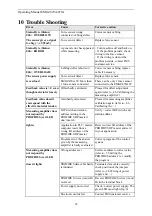
10
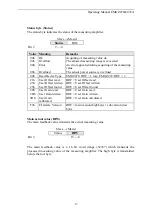
Trouble Shooting
Error
Cause
Corrective action
Status Byte (Status)
02h = OVERFLOW:
Force sensor wrong
connected / cabling defect
Correct sensor cabling
The sensor gives a signal
too big ( > ±9.92mV)
Force sensor defect
Replace force sensor
Status Byte (Status)
04h = ERROR
A general error has appeared
while measuring
– Turn machine off and back on.
– If the problem persists, check
wiring to the force sensor.
– If the wiring is ok and the
problem persists, contact FMS
customer service.
Status Byte (Status)
06h = OVERLOAD:
Cabling defect (short cut)
Correct sensor cabling, replace
cable if necessary
The sensor power supply
Force sensor defect
Replace force sensor
is overload
EMGZ470A.W: More than
1 force sensor connected
There can be only 1 force sensor
connected to the EMGZ470A.W
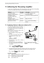
Feedback value is > 0 even
though material is loosely
Offset badly calculated
Proceed for offset adjustment
again (refer to „8.6 Calibrating the
measuring amplifier“)
Feedback value doesn’t
correspond with the
effective material tension
Gain badly calculated
Proceed for measuring amplifier
calibration again (refer to „8.6
Calibrating the…)
Measuring amplifier does
not respond by
PROFIBUS (red LED
DIP switch and station
address (setting in the
PROFIBUS DP master)
don’t match
Verify / correct DIP switch and
station address
lights)
Application in PLC / master
computer reads from a
wrong I/O address of the
PROFIBUS DP master
Detect correct I/O address of the
PROFIBUS DP master and set it
in your application
Program error; the answer
given by the measuring
amplifier is badly evaluated
Correct program of the control
system
Measuring amplifier does
not respond by
PROFIBUS (red LED
Wrong address set
Set slave address to correct value
(refer to „7.6 Setting the
PROFIBUS address“) or modify
the program
doesn’t light)
PROFIBUS data cable badly
terminated
Terminate data cable correctly;
check position of the jumpers
(refer to „7.4 Wiring of power
supply and …)
PROFIBUS wires (A and B)
reversed
Reverse PROFIBUS wires (A and
B) in the terminal block
Power supply not correct
Check / correct power supply. The
green LED must light (fig. 6)
Electronic unit defect
Contact FMS customer service


