21
Time Domain Reflectometry (TDR) Technology
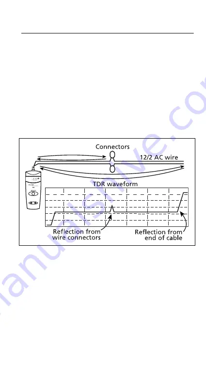
TDR technology examines this TDR waveform (see Figure 4),
looking at the sizes of the flat sections and the bumps. The
software decides which of the elements of the waveform is
most representative of the common problems encountered
in the wiring industries and reports the distance to that
element.
In the case of the waveform in Figure 4, the tester will report
the distance to the end of the wire run and will ignore the
small bump in the middle because it is too small to be
considered a problem.
cab04.eps
Figure 4. TDR Waveform
If more than one problem exists on the cable, the software
in the TS90 Cable Fault Finder only reports the nearest
problem.
The actual result of the measurement is the TIME to the
fault. The software in the tester converts the measured time
to a length by multiplying the time by the speed of the
electrical signal in that particular cable. That speed is
represented as a percentage of the speed of light and is
called the Velocity of Propagation (VOP).


