


Thermal Imager Camera
Installation
11
5.7.2. Connecting the Power Supply Cable
The power supply cable comes with a three-socket female M16 connector, assigned to the
cameras rear three pin male M16 connector. The corresponding end of the power supply cable
is carried out as a pig tail, to connect to an external power supply device. The standard cable
is about 5 mm (0.2 in) in outer diameter and is 7.5 m (25 ft) long. The cable withstands ambient
temperatures up to 80°C (176°F).
To connect the power to the ThermoView
®
camera, follow the steps below:
1. Connect the power connector to the camera
2. Tighten the outer nut of the female connector
3. Supply the open pig tail ends with power (12VDC - 26VDC). Take care about the right
polarity and connect the
brown
wire to Ground (-) and the
white
wire to +VDC
Figure 9: Power Connector
Be very careful in wiring the pig tailed end of the power cable
–
making sure
that the conductor colors on the cable match the correct terminals on the
power supply!
The cable shield must be connected to earth ground!
The external power supply must be in the range of 12 VDC to 26 VDC.
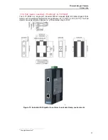
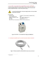
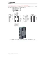
An external DIN rail mounted power supply is as an accessory available and allows to power
two cameras, I/O modules or fiber optic converters in parallel.
Please refer to section 7.1.9, 24 VDC 1.3 A industrial power supply, DIN rail mount (A-PS-DIN-
24V).


