Electrical
Installation
Tester
Making
Measurements
35
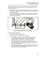
The earth resistance test is a 3-wire test consisting of two test stakes and the
earth electrode under test. This test requires an accessory stake kit. Connect
as shown in Figure 20.
•
Best accuracy is achieved with the middle stake at 62 % of the distance to
the far stake. The stakes should be in a straight line and wires separated to
avoid mutual coupling.
•
The earth electrode under test should be disconnected from the electrical
system when conducting the test. Earth resistance testing should not be
performed on a live system.
62
%
L
L
apx014f.eps
Figure 20. Earth Resistance Test Connection
To measure earth resistance:
1. Turn the rotary switch to the
position.
2. Press and release
. Wait for the test to complete.
•
The primary (upper) display shows the earth resistance reading.
•
Voltage detected between the test rods will be displayed in the
secondary display. If greater than 10 V, the test is inhibited.
•
If the measurement is too noisy, Err 5 will be displayed. (The
measured value accuracy is degraded by the noise). Press the down
arrow (
) to display the measured value. Press the up arrow (
) to
return to the Err 5 display.
•
If the probe resistance is too high, Err 6 is displayed. Probe resistance
may be reduced by driving the test stakes further into the earth or
wetting the earth around the test stakes.
Содержание 1652C
Страница 6: ...1652C 1653B 1654B Users Manual iv ...
Страница 8: ...1652C 1653B 1654B Users Manual vi ...

