


FW_F126PEGTP_v1901_04_EN.docx
Page 43
APPENDIX C: COMMUNICATION VARIABLES
General
The product is fitted with the Modbus communication protocol and can be equipped with various
physical interfaces like RS485 and RS232 (please see device datasheet for available options).
The tables below show the various variables that can be accessed through the communication.
Currently, the function codes supported are:
•
function code 3 “Read Holding Registers” (4x references);
•
function code 16 “Preset Multiple Registers” (4x references).
The table below shows the Modbus PDU addresses in a decimal format, followed by its hexadecimal
representation (0x0000). When the PLC address range is required (4x references are typically used
by PLCs), please add a value of 40001 to the Modbus PDU address. E.g. reading the serial number
of the product with PLC-based addressing means: 165 + 40001 = register 40166.
The variables that consist of a multiple register must always read/write in 1 single action!
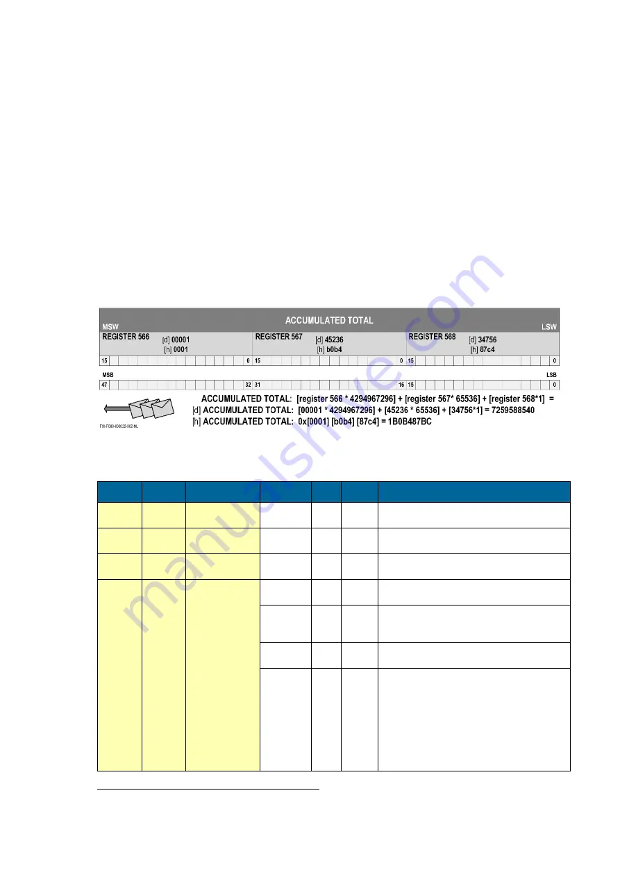
Refer to the illustration:
For this example it is assumed that the variable accumulated total has 3 registers (words) with
address 566, 567 and 568. When a transmission is done, register 566, which acts as the MSW,
arrives first with bit 15 which is the MSB of the lowest addressed word, but is also the MSB (bit 47)
of the complete variable that represents the Accumulated total.
Although most Modbus Masters will support variables that span 2 registers, variables spanning more
registers sometimes require you to manually calculate the resulting value.
For additional information regarding using your Modbus device, please read our ’General Modbus
Communication Protocol’ and ‘Modbus troubleshooting guide’ that are available through our website
or your distributor.
Runtime variables
PDU
ADDRESS
REGISTER VARIABLE
RUN TIME
NO.
REGISTERS
R/W
TYPE
VALUE / REMARKS
[d] 572
[h] 0x23C
40573
flow rate
2
r
uint32
0…9999999; Representatio
n: unit, time,
decimals depending on variables 48, 49, 50
[d] 566
[h] 0x236
40567
total
3
r
uint48
0…9999999999; Representation: unit, decimals
depending on variables 32, 33
[d] 560
[h] 0x230
40561
accumulated total
3
r
uint48
0…99999999999999; Represent
ation: unit,
decimals depending on variables 32, 33
[d] 540
[h] 0x21C
40541
temperature
2
r
uint32
0.00…9999999; Representation: normal
temperature, depending on variable 219
[d] 556
[h] 0x22C
40557
pressure
2
r
uint32
0.000…9999999; Representation: norm
al
compressibility, compressibility factor,
depending on variable 28, E3
[d] 588
[h] 0x24C
40589
TPC calculation
2
r
uint32
0…9999999; Representation: normal
temperature, depending on variable 219
[d] 516
[h] 0x204
40517
error status
(bitfield)
1
r
uint16
[d] 0 = no error
[d] 1 = display error
[d] 2 = data-storage error
[d] 3 = error 1 + error 2 simultaneously
[d] 4 =: initialization error
[d] 16 = PT100 ADC error
[d] 32 = Correction calculation factor error
[d] 64 = TPC calculation error
[d] 128 = PT100 sensor out of range error
Reading flow rate, total or accumulated total
:
The returned values are given including the decimals and represent the actual value. The given
value may differ from the value that is shown on the display
– this is due to the fact that the display
is limited in the number of digits and may have a slower update rate set.


