


Valtek FlowTop General Service Valve FCD VLENIM8610A4 11/18
6
No.
Check
Possible malfunction or safety related incident
6
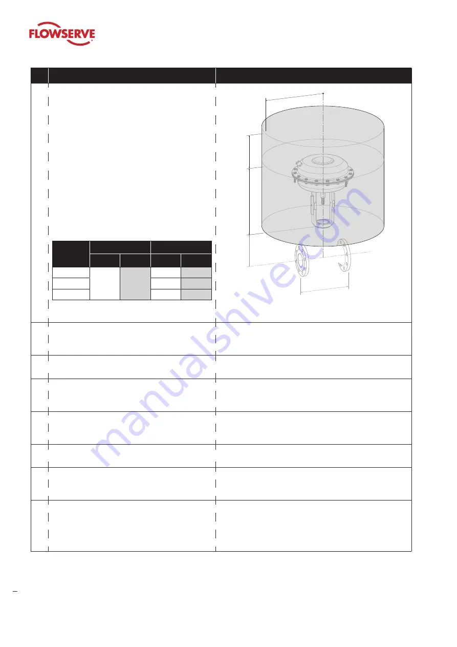
Confirm the actuator has enough overhead clearance
to disassemble the plug from the valve body.
Actuator
Code
Removal Space
≈ R
mm
inch
mm
inch
253
180
7.1
260
10.2
503
290
11.4
701
330
13.0
Table 2: Overhead clearance dimensions
Height of
valve
Face to face
dimensions
≈ R
Removal space
for actuator
Height of
actuator
Figure 6: Overhead clearance drawing
7
Confirm there are suitable piping lengths upstream
and downstream of the valve installation site in order
to minimize a sudden pressure surge in the flow.
Absence of suitable piping lengths can create critical operating
conditions and cause unacceptable levels of noise and
vibration.
8
Confirm removal of all hazards and ensure appropriate
protective measures are in place.
none
9
Confirm flow direction to ensure the correct valve
installation. Flow direction is indicated by the arrow on
the valve body.
Improper flow direction causes critical changes to operating
conditions that may damage the control valve.
10 Confirm that the air supply and instrument signal
lines are dry and clear of dirt and oil.
At a minimum, the instrument air must conform to ISA- 7.0.01-
1996 (ISO 8573-1 Compressed Air - Class 2) requirement or
those of the accessory manufacturer.
11 Confirm the valve is grounded in order to prevent an
electrical discharge.
Noncompliance may result in electrical discharges.
12 Confirm that the bonnet bolting of valves used in
NACE MR 0175 / MR 0103 or ISO 15 156 applications
are ventilated.
Do not cover or insulate over bonnet flange bolting !
13 Throttling control valves are typically equipped with
a pneumatic actuator and valve positioner. Refer to
the appropriate positioner manual for connections
and maximum air supplies.
The air supply must be limited to less than 87 psig (6 bar)
per the actuator serial plate. An air filter regulator should be
installed to ensure that the supply pressure to the pneumatic
actuator does not exceed the air supply pressure indicated on
the WW or EU serial plate.
Table 1: Basic safety massages for installing the valve
After these requirements are confirmed the valve can be installed and connected in the piping.


