


Valtek FlowTop General Service Valve FCD VLENIM8610A4 11/18
11
flowserve.com
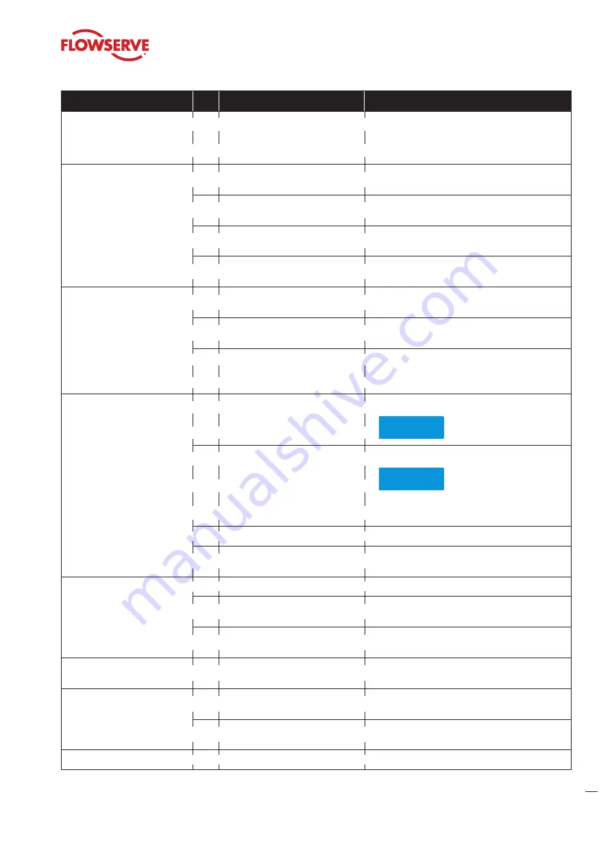
Defect
No.
Possible Causes
Remedy
Jerky stem movement
2.2
• Actuator not powerful enough
• Compare actuator specifications on the serial
plate with operation specifications of the facility. If
incompatible, contact customer service department
or contract partner
Stem travel less than full stroke
(0 to 100 %)
3.1
• Air supply pressure too low
• Provide air at the pressure stated on the serial plate
(European production only).
3.2
• Pneumatic actuators:
Improper handwheel position
• Move handwheel to limit position , otherwise
contact factory for information.
3.3
• Improperly adjusted or defective
positioner
• Readjust positioner to positioner manufacturer‘s
specification
3.4
• Foreign particles in valve seat or
damaged trim
• Contact customer service department or contract
partner
Excessive valve seat leakage
4.1
• Damaged sealing surfaces on
valve seat or plug
• Contact customer service department or contract
partner
4.2
• Foreign particles in seat area
• Contact customer service department or contract
partner
4.3
• Plug does not close fully
• Refer to No. 3.1 to 3.5
Leaking packing box system
5.1
• Compression force on packing box
too low
• Slightly retighten packing box
NOTICE
Make sure stem can still move.
5.2
• Worn packing
• Slightly retighten packing box
NOTICE
Make sure stem can still move.
If the packing does not stop leaking, contact
customer service department or contract partner
5.3
• Dirty stem
• Clean stem with suitable cleaning agent
5.4
• Damaged stem
• Contact customer service department or contract
partner
Leaking bonnet gasket
6.1
• Gasket compression is too low
• Properly retighten bonnet bolting nuts crosswise
6.2
• Gasket defective
• Contact customer service department or contract
partner
6.3
• Corrosion
• Contact customer service department or contract
partner
Leaking body
7.1
• Corrosion or high velocity related
damage
• Contact customer service department or contract
partner
No limit switch signal
8.1
• Power supply to limit switch
interrupted
• Check power supply
(connections, circuit breakers, voltage)
8.2
• Limit switch out of adjustment
• Readjust limit switch operating distance; see limit
switch data sheet
Unstable positioner
9.1
• Defective positioner
• See user instruction of the positioner manufacturer
Table 8: Trouble-shooting


