background image

 R and RX SLURRY Pump USER INSTRUCTIONS ENGLISH  

71569242 03-11 (E)


Page 44 of 56 

flowserve.com


® 

Preparation for Operation. 

e)  It is recommended that the pump not be packed until 

required. Refer to stuffing box packing procedure in 

this section. Protect the stuffing box bore and seal 

area with clean dry rags. 


6.11 Impeller axial clearance adjustment 

 This procedure should not be used on units 

with mechanical seals if the design is such that a 

liquid seal cannot be maintained when the rotor is 

moved axially against the liners. 

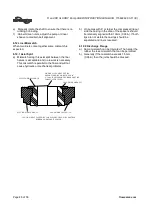
A blind flange must be installed on the 

suction to compress the liner nozzle as it will be in 

service. If this is not done clearance could be lost 

cause impeller to rub against the liner causing 

damage to pump components. 


NEVER ATTEMPT TO CHANGE THE 

CLEARANCE WHEN THE PUMP IS RUNNING. 


6.11.1 Frames 1-4 

If the coupling has limited axial adjustment capability, 

the pump and driver must be uncoupled prior to 

adjusting the clearance in order to permit free 

movement. 

 Install blind flange or pipe spool on 

suction. 

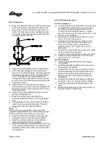
a)  Loosen the two set screws retaining the deflector 

[2540] and check that the deflector is free to move 

axially on the shaft. 

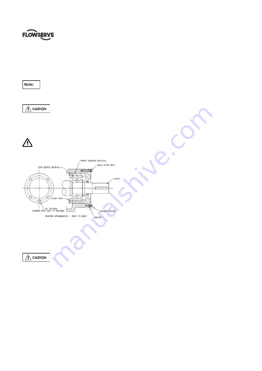
b)  Loosen the thrust bearing housing jam nuts and 

back off the three jacking screws at least 1.5 mm 

(0.060 inch). 

c)  Move the rotor towards the suction side liner 

[1916.1] by tightening the three hold-down 

capscrews evenly and uniformly until the impeller 

[2200] just touches the wear plate.  This can be 

best established by rotating the shaft and stopping 

the forward motion at the first sign of rubbing.  If 

the shaft cannot be rotated, back off the bearing 

housing with the jacking screws until a just 

detectable rub is obtained.  Check that the gap 

between the two machined faces of the thrust 

bearing housing [3230] and the bearing frame 

[3130] are parallel within 0.076 mm (0.003 inch).  

Adjust the jack screws and hold down capscrews 

as required to achieve this parallelism.  When the 

impeller [2200] just touches the wear plate [1915] 

and the thrust bearing housing [3230] is parallel to 

the bearing frame [3130] the axial clearance 

between the impeller and wear plate is zero.   

6.11.1.1 Option1 

a)  Place a dial indicator, set to end of shaft [2110] or 

on housing [3230] face. 

b)  Set indicator reading to zero (0). 

c)  Note required impeller clearance. 


6.11.1.2 Option 2 

a)  Measure and record the axial gap between the 

thrust bearing housing flange and bearing frame 

end face.  Determine the required impeller axial 

running clearance from Section 3 and add this to 

the above measurement to establish the required 

gap setting. 


6.11.1.3 Setting Axial Clearance 

a)  Loosen the thrust bearing housing hold down 

capscrews slightly and tighten the jack screws. 

Until the required dial indicator reading (6.11.1.1) 

or housing gap reading (6.11.1.2) is achieved.  

b)  Alternately and gradually tighten the hold down 

capscrews and jack screws until the required gap 

setting is achieved at each hold down capscrew 

location.  Note that the gap at each jack screw will 

be slightly larger as a result of minor elastic 

distortion of the thrust bearing housing flange 

caused by the high pre-load forces.  The gap 

setting at any set of screws must be the same 

within 0.076 mm (0.003 in.). Careful attention to 

this procedure will help ensure long thrust bearing 

life. 

c)  While preventing the jack screws from rotating, 

tighten the jam nuts to lock them in position. 

d)  Adjust the axial position of the deflector [2540] so 

that it is clear of the line bearing cover [3260] by 

approximately 0.75 mm (0.030 in.) and tighten the 

setscrews firmly.  Excessive tightening may mar 

the shaft. 

e)  Manually rotate the shaft to ensure that there is no 

rubbing or binding. 

f)  On belt driven units, adjust the pump or driver 

sheave to maintain belt alignment.  (Refer to 

Section 4.5.2.2). 

g)  Check the alignment on direct driven units (refer 

Содержание R

Страница 1: ...s equipment R and RX Installation Operation Maintenance Centrifugal Rubber Lined Slurry Pump PCN 71569242 03 11 E incorporating 2162 EID Original instructions Компания ПромХимТех официальный дистрибьютор насосов Flowserve www promhimtech ru Тел 8 800 250 01 54 e mail zakaz promhimtech ru ...

Страница 2: ...9 Electrical connections 26 4 10 Protection systems 27 5 COMMISSIONING START UP OPERATION AND SHUTDOWN 27 5 1 Pre commissioning procedure 27 5 2 Pump lubricants 28 5 3 Direction of rotation 29 5 4 Guarding 29 5 5 Priming and auxiliary supplies 29 5 6 Starting the pump 29 5 7 Operating the pump 30 5 8 Stopping and shutdown 31 5 9 Hydraulic mechanical and electrical duty 31 PAGE 6 MAINTENANCE 32 6 1...

Страница 3: ... 47 General assembly drawings see 8 49 Grouting 4 4 21 Guarding 5 4 29 Handling 2 2 9 Hydraulic mechanical and electrical duty 5 9 31 Lifting 2 3 11 Location 4 1 21 Lubrication schedule see 5 2 Pump lubricants 28 Maintenance schedule 6 2 32 Piping 4 7 22 Priming and auxiliary supplies 5 5 29 Reassembly see 6 10 Assembly 37 Replacement parts see 6 3 and 6 4 32 Safety electrical see 4 9 26 Safety pr...

Страница 4: ...d any additional Approvals cover important safety aspects relating to machinery and equipment and the satisfactory provision of technical documents and safety instructions Where applicable this document incorporates information relevant to these Directives and Approvals To confirm the Approvals applying and if the product is CE marked check the serial number plate markings and the Certification Se...

Страница 5: ...e applicable training Always coordinate repair activity with operations and health and safety personnel and follow all plant safety requirements and applicable safety and health laws and regulations 1 6 3 Safety action This is a summary of conditions and actions to prevent injury to personnel and damage to the environment and to equipment For products used in potentially explosive atmospheres sect...

Страница 6: ...low the recommended minimum flow continuously will cause damage to the pump and mechanical seal DO NOT RUN THE PUMP AT ABNORMALLY HIGH OR LOW FLOW RATES Operating at a flow rate higher than normal or at a flow rate with no back pressure on the pump may overload the motor and cause cavitation Low flow rates may cause a reduction in pump bearing life overheating of the pump instability and cavitatio...

Страница 7: ...perature varies and the pump could be installed in different hazarous atmospheres In this case the user is responsible for ensuring that the pump surface temperature does not exceed that permitted in the particular hazardous atmosphere If an explosive atmosphere exists during the installation do not attempt to check the direction of rotation by starting the pump unfilled Even a short run time may ...

Страница 8: ...input to the liquid This can occur if the pump is stationary or running Bursting of liquid containing parts due to freezing must be avoided by draining or protecting the pump and ancillary systems Where there is the potential hazard of a loss of a seal barrier fluid or external flush the fluid must be monitored If leakage of liquid to atmosphere can result in a hazard install a liquid detection de...

Страница 9: ... of nameplate see the Declaration of Conformity or separate documentation included with these User Instructions 1 7 2 Safety labels MECHANICAL SEAL WARNING ROTATION WARNING P N 2113931 001 P N 2113932 001 GROUT WARNING LIFTING WARNING P N 2113934 001 P N 9901701 001 LUBRICATION WARNING QF 440 R01 2124841 Oil lubricated units only ...

Страница 10: ...nal factors flow rate pipework design and acoustic characteristics of the building and so the values given are subject to a 3 dBA tolerance and cannot be guaranteed Similarly the motor noise assumed in the pump and motor noise is that typically expected from standard and high efficiency motors when on load directly driving the pump Note that a motor driven by an inverter may show an increased nois...

Страница 11: ...ted units are lubricated at the factory during assembly Turn the rotor over by hand at least once a week to maintain a protective film on the bearing components 2 4 2 Long Term Storage More than precautions are required if long term storage in excess of 90 days from factory shipment is unavoidable The internal surfaces of the pump should be sprayed with a rust preventative such as a water soluble ...

Страница 12: ...d and openings are provided with covers or plugs Shaft packing when required is shipped with the pump and should not be installed until the pump is ready to run Mechanical seals when provided are factory installed and adjusted prior to shipment The axial impeller running clearance is preset at the factory but should be checked prior to final alignment in case of tampering These User Instructions a...

Страница 13: ... your installation It is typical and factors such as temperature materials and seal type may influence this data If required a definitive statement for your particular application can be obtained from Flowserve 3 4 1 Operating limits 3 4 1 1 Temperature Liner Materials Maximum Operating Temperature Natural Rubber soft 65ºC 150ºF Natural Rubber Hard 80ºC 176ºF Nitrile 93ºC 200ºF Neoprene 100ºC 212º...

Страница 14: ...L 360 BHN 2 3 Impeller Spacer HARD STEEL 360 BHN 2 3 Shaft Sleeve ASTM A743 CG3M 1 Shaft AISI 1045 Gland Halves ASTM A743 CF8M 316 Pipe Plugs Stuffing Box C I 2 Gland Studs And Nuts AISI 316 Liner Studs Nuts AISI 1018 1020 Steel PACKING SYNTHETIC FIBRE SEAL CAGE HALVES ASTM A743 CG8M GASKETS CASING SYNTHETIC FIBRE GASKETS SLEEVE TEFLON O RINGS BUNA N 120o C MAX MISC FASTNERS PARTS STEEL 1 Nickel C...

Страница 15: ...5 64 2 5 76 3 64 2 5 76 3 76 3 102 4 127 5 MAX SPHERE SIZE mm in 10 0 38 15 0 6 23 0 9 15 0 6 23 0 9 31 1 2 43 1 7 48 1 9 VVK wet kg m lb ft 0 12 2 8 0 12 2 8 0 11 2 6 0 12 2 8 0 11 2 6 0 21 4 9 0 44 11 0 82 19 PUMP WEIGHT kg Ibs 195 430 218 480 241 530 241 530 264 580 286 630 391 860 486 1 070 IMPELLER CLEARANCE mm in O D SLEEVE mm in La STUFFING BOX mm in DEPTH OF BOX mm in PACKING SIZE mm in RE...

Страница 16: ...ER DIA UNDER SLEEVE 41 27 1 625 6307 6311 1 88 63 5 2 50 25 4 1 00 3307 7309 BUA 25 4 1 00 41 27 1 625 168 6 61 193 8 7 63 MINIMUM 3 YEARS 8 06 11 00 204 7 180 7 09 207 8 8 18 LINE BEARING O RING N A 246 NAT 417350 LINE BEARING LIP SEAL C R 9998 C R 19832 NAT 472492 263 7314 BUA 279 4 259 1 R 090 2 R 090 3 R 090 3 R 091 3 R 111 34 93 C R 16246 2 500 6316 1 375 91 9 3 62 63 5 240 250 BEARING SEALS ...

Страница 17: ...0 8 in 2 10 2 80 3 60 3 20 2 00 WK2 wet kg m 2 1 81 3 62 8 83 12 6 86 79 lb ft 2 43 86 209 298 2056 PUMP WT kg 832 1009 1582 2100 7273 lbs 1830 2220 3480 4620 16000 IMPELLER CLEARANCE mm 1 14 1 5 1 8 in 0 045 0 06 0 07 O D SLEEVE mm 95 25 120 7 184 1 in 3 75 4 75 7 250 I D STUFFING BOX mm 127 152 4 222 3 in 5 00 6 00 8 75 STUFFNG BOX DEPTH mm 116 3 116 3 165 in 4 58 4 58 6 5 PACKING SIZE mm 15 9 x...

Страница 18: ...26C 513 20 20 355 13 96 MINIMUM 3 YEARS BEARING SEALS NAT 417379 NAT 417511 C R 63700 GARL 53x3409 GARL 53x3275 C R 57510 874 34 41 699 27 50 24034HL 29334E 23134HL 146 05 5 75 267 269 5 75 11 00 276 269 QJ322 NU322 C R 42419 NAT 416556 85 72 160 6 30 82 55 108 4 25 7 25 91 9 3 62 146 1 184 2 18 R 416 50 8 2 00 98 6 3 88 SHAFT AND BEARING DATA 139 7 5 50 BEARING SPAN NAT 417191 THRUST BEARING O RI...

Страница 19: ...o allow the bolts to be moved to conform with the holes in the baseplate The bolts should be sufficiently long to allow for wedges or shims or levelling nuts under the baseplate and a washer heavy hex nut and hex jam nut for retention Since baseplate levelling is performed after the foundation has cured it is best to use extra long bolts that can be shortened after the installation is complete 4 4...

Страница 20: ...baseplate such that the correct spacing is obtained between the two half couplings In the case of electric motors such as those with sleeve bearings it may be necessary to run the motor to establish the rotor magnetic center Consult the manufacturer s instruction manual for details The purpose of the alignment procedure is to ensure that the pump and driver shafts are in parallel and angular align...

Страница 21: ...ce build up associate with the pump coupling and driver it may be necessary to match up the two coupling hubs in the most advantageous relative angular position in order to achieve an acceptable alignment Do not install the coupling spacer or sleeve until grouting is complete and cured and the alignment is re checked When the electric motor has sleeve bearings it is necessary to ensure that the mo...

Страница 22: ...d levelling nuts should be removed or backed off Tighten down baseplate to the new grout to put bolts in tension and ensure rigidity of structure Install jam nuts and cut the bolts to the desired length Finish grouting isolated areas Fill the baseplate including pump and driver support pedestals with concrete Trowel and slope the surface to give suitable drainage 4 7 Piping Protective covers are f...

Страница 23: ...a seal and retain the liner nozzle At assembly and prior to installing piping ensure that the lip is properly seated in the recess of the casing 4 7 1 4 Spool Installation The sketch below illustrates that a short spool is recommended to connect to the flange The spool should be moved perpendicular to the flange so that the rubber sealing lip is not dislodged If the spool is slid into the flange f...

Страница 24: ...f 56 flowserve com Once the spool is installed additional suction piping may be installed These flange joints will require gaskets Figure 8D illustrates the assembly of other piping flange facings at other joints then the pump may be raised of flat Spool piece Suction Piping ...

Страница 25: ...340 1200 6100 4500 2980 2200 4610 3400 6670 1500 5340 1200 8000 1800 350 14 6370 4700 3120 2300 4750 3500 8900 2000 7120 1600 5780 1300 6370 4700 3120 2300 4750 3500 7120 1600 5780 1300 8900 2000 400 16 7320 5400 3660 2700 5420 4000 10230 2300 8450 1900 6670 1500 7320 5400 3660 2700 5420 4000 8450 1900 6670 1500 10230 2300 450 18 8200 6050 4200 3100 6100 4500 11570 2600 9650 2170 7560 1700 8200 60...

Страница 26: ... to feed the gland packing with liquid to provide lubrication and prevent the ingress of air This is normally achieved with a supply from the pump discharge volute to the stuffing box A control valve is fitted in the line to enable the pressure to the gland to be controlled If the pumped liquid is dirty and cannot be used for sealing a separate clean compatible liquid supply to the gland at 1 bar ...

Страница 27: ... or prevent it from being started This is particularly relevant if the pump is handling a flammable liquid If leakage of product from the pump or its associated sealing system can cause a hazard it is recommended that an appropriate leakage detection system is installed To prevent excessive surface temperatures at bearings it is recommended that temperature or vibration monitoring are carried out ...

Страница 28: ...Shell Shell Tellus 32 Shell Tellus 37 Shell Tellus 01 C 68 Shell Tellus 01 68 Shell Tellus 01 C 46 Shell Tellus 01 46 Texaco Rando Oil HD 32 Rando Oil HD AZ 32 Rando Oil 68 Rando Oil HD C 68 Rando Oil 46 Rando Oil HD B 46 Wintershall BASF Group Wiolan HN32 Wiolan HS32 Wiolan HN68 Wiolan HS68 Wiolan HN46 Wiolan HS46 5 2 2 Recommended grease lubricants Grease Grease nipples NLGI 2 NLGI 3 Temp range ...

Страница 29: ...is viewed from the driver To avoid dry running the pump must either be filled with liquid or have the flexible coupling disconnected before driver is switched on If maintenance work has been carried out to the site s electricity supply the direction of rotation should be re checked as above in case the supply phasing has been altered 5 4 Guarding Guarding is supplied fitted to the pump set Fastene...

Страница 30: ...o avoid being caught up by the pump shaft Shaft guards must be replaced after the gland adjustment is complete Never run gland packing dry even for a short time 5 7 3 Pumps fitted with mechanical seal Mechanical seals require no adjustment Any slight initial leakage will stop when the seal is run in Before pumping dirty liquids it is advisable if possible to run in the pump mechanical seal using c...

Страница 31: ...rtional to SG It is therefore important to check that any change in SG will not overload the pump driver or over pressurize the pump 5 9 2 Viscosity For a given flow rate the total head reduces with increased viscosity and increases with reduced viscosity Also for a given flow rate the power absorbed increases with increased viscosity and reduces with reduced viscosity It is important that checks ...

Страница 32: ...arning board on the fuse box or main switch with the words Machine under repair do not connect Never clean equipment with inflammable solvents or carbon tetrachloride Protect yourself against toxic fumes when using cleaning agents 6 2 Maintenance schedule It is recommended that a maintenance plan and schedule is adopted in line with these User Instructions to include the following a Any auxiliary ...

Страница 33: ...anti friction bearings will vary from unit to unit depending on ambient and fluid temperature The rise above ambient should not normally exceed 55 C 99 F or a combined maximum of 95 C 204 F f A continuously rising temperature or an abrupt temperature rise indicates a problem If these symptoms occur stop the pump immediately and investigate the cause TIME TEMPERATURE Grease change every 4 000 hours...

Страница 34: ...change to the original design specification modification or use of a non standard part will invalidate the pump s safety certification 6 3 2 Storage of spares Spares should be stored in a clean dry area away from vibration Inspection and re treatment of metallic surfaces if necessary with preservative is recommended at 6 monthly intervals Rubber components must be protected from direct sunlight an...

Страница 35: ...erials should be available since they will be required for reassembly a Isolate motor and lock off electrical supply in accordance with local regulations b Isolate suction and discharge valves c Remove guards d Disconnect the coupling halves or remove belts from sheaves e Drain pump casing Remove any auxiliary piping if applicable f Disconnect stuffing box cooling water and auxiliary piping g Drai...

Страница 36: ...tly high to ensure end of the shaft does not come into contact with the floor or table e Remove the thrust bearing hold down bolts and remove shaft assembly for the bearing frame 3130 6 8 5 Line bearing a Lay the shaft 2110 horizontal and support with wooden V Blocks b Only if necessary remove the line bearing 3011 from the shaft Bearings removed can easily be damaged and undetected until pump is ...

Страница 37: ...leeve are replaced at the same time 6 9 5 Bearing isolators labyrinths or lip seals if fitted a The lubricant bearings and bearing housing seals are to be inspected for contamination and damage If oil bath lubrication is utilised these provide useful information on operating conditions within the bearing housing b If bearing damage is not due to normal wear and the lubricant contains adverse conta...

Страница 38: ...l return slot at the bottom the thrust bearing housing bore Tighten the capscrews evenly ensuring that the clamp ring is not distorted and gap to the bearing housing is even all around Tighten in accordance with Table 6 6 6 10 3 2 Frame 4 pumps a Place the thrust bearing clamp ring 2542 loosely over the shaft on the largest diameter b Install the 4 point angular contact bearing 3031 on the shaft 2...

Страница 39: ...ing 3230 and assemble it over the thrust bearings Care must be taken to prevent damage of the seal on the shaft 6 10 4 Frame assembly 6 10 4 1 Frame 1 2 a Place the pedestal with the large flange flat on a work surface table b Lift the bearing cartridge vertical and assemble to the pedestal Secure in position The orientation of the pedestal feet and the tapped holes for the rear support foot shoul...

Страница 40: ... Install the cartridge hold down bolts with the heavy plate washers but do not tighten j Install the adjusting screw 6576 between the ribs of the bearing cartridge 3130 The fixture may be installed on either side of frame as convenient for the installation 6 10 5 Line Bearing Cover 6 10 5 1 Frames 1 4 a Carefully install the lip seal 4300 in the line bearing cover 3260 by pressing it squarely into...

Страница 41: ... 4 1 All sizes a Lift the casing 1212 and install to the pedestal 3120 b Secure casing to pedestal 6 10 6 4 2 Frame 6 only The babbit fits of the glandside casing to the pedestal and to the stuffing box are loose It is necessary check the concentricity of the stuffing box and the shaft with dial indicators or feeler gauges If necessary loosen studs and reposition stuffing box and or the gland side...

Страница 42: ...ely against the sleeve may cause serious damage to pump components The thread is designed so that during operation the impeller will tend to tighten onto shaft Therefore a clockwise shaft rotation looking from coupling end will screw impeller on e Release the thrust bearing housing hold down bolts and tighten the jacking screws to pull the impeller back to the stuffing box head 4100 The stuffing b...

Страница 43: ...ffective the packing must remain soft and pliable If stuffing box friction is so great that the pump shaft cannot be turned by hand the box is not properly packed 6 10 10 2 Mechanical seal These details are specific to non cartridge seals therefore they may not apply Refer to any special instructions supplied with the mechanical seal a Before the mechanical seal can be installed the pump must be a...

Страница 44: ...parallel within 0 076 mm 0 003 inch Adjust the jack screws and hold down capscrews as required to achieve this parallelism When the impeller 2200 just touches the wear plate 1915 and the thrust bearing housing 3230 is parallel to the bearing frame 3130 the axial clearance between the impeller and wear plate is zero 6 11 1 1 Option1 a Place a dial indicator set to end of shaft 2110 or on housing 32...

Страница 45: ...is achieved e Tighten the hold down nut d Adjust the axial position of the deflector 2540 so that it is clear of the line bearing cover 3260 by approximately 0 75 mm 0 030 in e Manually rotate the shaft to ensure that there is no rubbing or binding f On belt driven units adjust the pump or driver sheave to maintain belt alignment Refer to Section 4 5 2 2 g Check the alignment on direct driven unit...

Страница 46: ... mechanical problems b On pumps with 8 or larger the compressed lip out side the casing in the area of the spacers should be relatively aligned within 10mm 0 38in If both lips are not visible the casings should be separated and liners reseated 6 12 2 Discharge Flange a Some mismatch can be tolerated The harder the rubber the less mismatch that can be permitted b Generally if the mismatch exceeds 1...

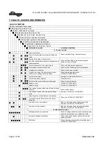
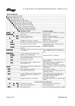
Страница 47: ...ir leaks into pump through mechanical seal sleeve joints casing joint or pipe plugs Check and replace faulty parts CONSULT FLOWSERVE Foot valve too small Investigate replacing the foot valve Foot valve partially clogged Clean foot valve Inlet of suction pipe insufficiently submerged Check out system design Speed too low CONSULT FLOWSERVE Speed too high CONSULT FLOWSERVE Total head of system higher...

Страница 48: ...tory check bearings for excessive wear Impeller out of balance resulting in vibration Check and CONSULT FLOWSERVE Abrasive solids in liquid pumped Internal misalignment of parts preventing seal ring and seat from mating properly Mechanical seal was run dry Check mechanical seal condition and source of dry running and repair Internal misalignment due to improper repairs causing impeller to rub Chec...

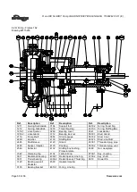
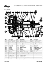
Страница 49: ...12 Impeller Nut 3011 Radial ball bearing Line brg 3031 Thrust bearing 3110 Bearing bracket 3230 Thrust bearing housing 3260 Bearing Cover 3712 Bearing lock nut 3840 Lubricating pipe 3856 Oil site gauge 4120 Gland 4130 Packing 4132 Stuffing Box Bushing 4134 Lantern Ring 4260 Spring 4300 1 Radial lip seal Line bearing 4300 2 Radial lip seal Thrust Brg 4590 Gasket Sleeve 4610 1 O ring shaft sleeve 46...

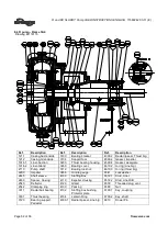
Страница 50: ... 6572 1 Stud Gland 2110 Pump shaft 3856 Oil site gauge 6572 2 Stud Liner 2200 Impeller 4100 Stuffing Box 6572 3 Stud Liner SB 2445 Shaft sleeve 4120 Gland 6578 1 Threaded plug pipe 2460 Spacer Impeller 4130 Packing 6578 2 Threaded plug vent 2540 Deflector 4132 Stuffing box bushing Protector plate 6580 Nut wearplate 2542 Clamping ring 4134 Lantern Ring 6700 1 Key coupling 3011 Radial ball bearing 4...

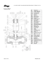
Страница 51: ...916 2 Liner Gland 3856 Oil site gauge 6572 1 Stud Gland 2110 Pump shaft 4100 Stuffing Box 6572 2 Stud Liner 2200 Impeller 4110 Expeller Housing 6576 Adjusting Screw fixture 2250 Expeller 4120 Gland 6578 Threaded plug vent 2445 Shaft sleeve 4130 Packing 6580 Nut wearplate 2460 Spacer Impeller 4134 Lantern Ring 6700 1 Key coupling 2540 Deflector 4300 1 Radial lip seal Line brg 6700 2 Key shaft 2542 ...

Страница 52: ...6 2 Liner Gland 3260 Bearing cover 4610 2 O ring Line brg 2110 Pump shaft 3712 Bearing lock nut 4610 3 O ring thrust brg 2200 Impeller 3856 Oil site gauge 6541 Lockwasher 2445 Shaft sleeve 4100 Stuffing Box 6572 1 Stud Liner 2460 Spacer Casing 4110 Expeller Housing 6572 2 Stud Liner SB 2540 Deflector 4120 Gland 6578 Threaded plug vent 2542 Clamping ring 4130 Packing 6580 Nut 3011 Radial ball beari...

Страница 53: ...t 3011 Radial ball bearing 3031 Thrust bearing 3110 Bearing bracket 3120 Bearing support pedestal 3230 Thrust bearing housing 3260 Bearing Cover 3712 Bearing lock nut 3840 Lubricating pipe 3856 Oil site gauge 4120 Gland 4130 Packing 4132 Stuffing Box Bushing 4134 Lantern Ring 4260 Spring 4300 1 Radial lip seal Line brg 4300 2 Radial lip seal Thrust Brg 4590 1 Gasket Inboard Brg 4590 2 Gasket Outbo...

Страница 54: ...for inclusion into User Instructions such as for a driver instrumentation controller sub driver seals sealant system mounting component etc are included under this section If further copies of these are required they should be obtained from the purchaser for retention with these User Instructions Where any pre printed set of User Instructions are used and satisfactory quality can be maintained onl...

Страница 55: ...R and RX SLURRY Pump USER INSTRUCTIONS ENGLISH 71569242 03 11 E Page 55 of 56 flowserve com NOTES ...

Страница 56: ...ion 5215 North O Connor Blvd Suite 2300 Irving Texas 75039 5421 USA Telephone 1 972 443 6500 Fax 1 972 443 6800 Europe Middle East Africa Flowserve FSG Italy Worthing S P A Via Rossini 90 92 20033 Desio Milan Italy Telephone 39 0362 6121 Fax 39 0362 628 882 Latin America and Caribbean Flowserve Corporation 6840 Wynnwood Lane Houston Texas 77008 USA Telephone 1 713 803 4434 Fax 1 713 803 4497 Asia ...

Отзывы: