background image

23

8.1 Grounding screw

The grounding screw, located inside the
positioner cover, should be used to prov-
ide the unit with an adequate and reliable
earth ground reference. This ground
should be tied to the same ground as the
electrical conduit. Additionally, the
electrical conduit should be earth
grounded at both ends of its run. The
grounded scrrew must not be used to
termingate signal shield wires.

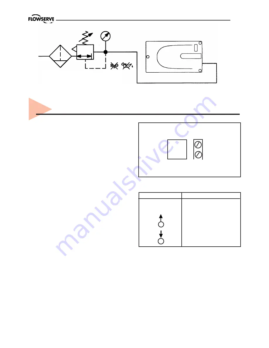
Figure 8. Connections

Electrical connections:

  signal cable

with cable passage (1/2” NPT, or M20 x
1,5) to terminals 2 x 2,5 mm.

Input signal:

 4 – 20 mA

NOTE:


Observe the minimum

requirements of voltage and equivalent
electrical load:

8 VDC at 20 mA

The performance is ensured only for a
minimum input current of 3,6 mA.

For wiring, the following notes should be
observed:

NOTE:


The input loop current signal to

the 

PMV D20


should be in shielded cable.

Shields must be tied to a ground at only
one end of the cable to provide a place
for environmental electrical noise to be
removed from the cable. In general,
shield wire should be connected at the
source. (Figure 8).

Connect the 4-20 mA current source to
ter1 and -2, see connection ta-
ble.

8.  Wiring and grounding guidelines


 Connection             Description

+1

Input  +4-20 mA

–2

Input  –4-20 mA

Pneumatic output
signal (outlet)

Air supply

 +         –

4 - 20 mA

      IN

1      2

ISO 8573 2.2.2
ISA 7.0.01.-1996 Class 2

2 - 6 bar
30 - 90 Psi

µ

Содержание PMV D20

Страница 1: ...Installation Operation Maintenance PMV D20 Digital Positioner ...

Страница 2: ...ng on a linear pneumatic actuator 17 6 3 Rotary actuators 19 7 Tubing positioner to actuator 22 8 Wiring and grounding guidelines 23 8 1 Grounding screw 23 8 2 Electromagnetic compability 24 8 3 Compliance voltage 24 9 Operation 25 9 1 Operation 25 9 2 Start up 25 9 3 Calibration 25 9 4 Set of Direct or Reverse action 26 9 5 Show gain setting 26 9 6 Change gain setting 27 10 Limit switches 4 20 mA...

Страница 3: ...substantial property damage can occur if proper precautions are not taken CAUTION indicates that minor personal injury and or property damage can occur if proper precautions are not taken In most cases FLOWSERVE valves actuators and accessories are designed for specific applications e g with regard to medium pressure temperature For this reason they should not be used in other applications without...

Страница 4: ...t fitted under tension Fire protection must be provided by the user 1 6 Spare parts Use only FLOWSERVE original spare parts FLOWSERVE cannot accept responsibility for any damages that occur from using spare parts or fastening materials from other manufactures If FLOWSERVE products especially sealing materials have been on store for longer periods check these for corrosion or deterioration before u...

Страница 5: ...ht to refuse taking back products that are inadequatelypackagedandtherebypresentssafetyand orhealthrisks to the staff The manufacturer will not reimburse you for the shipping cost flange faces to prevent the ingress of fo reign materials These caps should not be removed until the valve is actually mounted into the system 1 9 Valve and actuator variations These instructions cannot claim to cover al...

Страница 6: ...low ambient tempera ture particle size below five microns one micron recommended and oil con tent not to exceed one part per million 3 The PMV D20 is a two wire loop powered 4 20 mA input digital valve positioner The PMV D20 positioner controls actuators with linear and rotary mountings The PMV D20 is completely powered by the 4 20 mA input signal The minimum input signal required to function is 3...

Страница 7: ...crew terminals 2 5 mm2 AWG 14 Operating Temperature 20 to 85 C 40 to 85 C optional Storage temperature 40 to 85 C Air delivery capacity 7 Nm3 h 6 bar 3 bar diff pressure Air delivery capacity Double acting 7 Nm3 h 6 bar 3 bar diff pressure Air consumption Single acting 0 120 Nm3 h 6 bar Air consumption Double acting 0 120 Nm3 h 6 bar Cv air delivery Single acting 0 12 Cv air delivery Double acting...

Страница 8: ...ge 8 VDC Load current 1mA I 3mA Voltage range 5 25 VDC Hysteresis max 0 2 Temp range 25 to 100 C 248 to 373 F Namur sensors Type P F SJ2 SN Normal Voltage 8 VDC Load current 1mA I 3mA Voltage range 5 25 VDC Hysteresis max 0 2 Temp range 40 to 100 C 233 to 373 F Namur sensors Type P F SJ2 S1N Normal Voltage 8 VDC Load current 1mA I 3mA Voltage range 5 25 VDC Hysteresis max 0 2 Temp range 25 to 100 ...

Страница 9: ...Operating time 1 0 ms Transmitter Power supply 12 28 VDC Output 1 22 mA Resolution 0 1 Linearity 0 5 Load impedance 600 ohm at 12 VDC and 20mA Alarm Output Supply 3 28 VDC Output 20mA 24 VDC 4 3 Type sign ...

Страница 10: ...it not included G Cover and Indicator PVA PMV Black cover Arrow indicator PVB PMV Black cover No indicator PVD PMV Black cover Dome indicator H Temperature seals Z Standard 20 C to 85 C 4 F to 185 F Q Low temp 40 C to 85 C 38 F to 185 F I Input signal Protocol 4 4 20 mA none 5 4 20 mA HART J Feedback option 4 20 mA transmitter switches X No feedback option T 4 20 mA transmitter only S Limit switch...

Страница 11: ...11 4 5 Control Drawing ...

Страница 12: ...12 4 6 Certificates ...

Страница 13: ...13 ...

Страница 14: ...14 ...

Страница 15: ...15 ...

Страница 16: ...plifier is measured and relayed to the inner loop control circuit This two stage control provides for more responsive and tighter control than is possible with a single stage control algorithm The pneumatic amplifier controls the airflow to the actuator The change of pressure and volume of the air in the actuator causes the valve to stroke As the valve approaches the desired position the differenc...

Страница 17: ...actuators according to NAMUR lEC 534 part 6 refer to Figure 5 After installation ensure all screw connections are tightened correctly and all moving parts are free from excessive friction 6 Mounting and installation 6 2 Mounting of the PMV D20 positioner on a linear pneumatic actuator NAMUR IEC 534 part 6 See Figure 3 The mounting of a rod actuator kit according to IEC 534 part 6 is described in a...

Страница 18: ...ed in the slot of the take off arm and the follower arm is positioned at a right angle to the outer edge of the positioner 4 Tighten all screws and nuts NOTE A slight unsymmetrical mounting increases the linearity deviation but does not affect the performance of the device Depending on the actuator size and stroke it may be necessary to flip the take off arm Figure 3 by 180 and attach it to the op...

Страница 19: ...eral distance should be approximately 5 mm 0 2 inches to pre vent bending of the feed back mechanisim 6 3 Rotary actuators Mounting the PMV D20 positioner on a quarter turn actuator closed or open by spring The mounting of a pneumatic double pis ton part turn valve actuator in accordance with VDI VDE 3845 is described as an example by using the following equipment Quarter turn valve actuator Rack ...

Страница 20: ...it pin on valve stem Fit lever arm to positioner shaft Fit and check O rings and positioner to actuator and secure with 2 x screws 2 No tubing needed it s integrated with actuator fit plug in positioner out port Linear actuator VDI VDE 3847 Direct mounting integrated tubing Check O rings Install bracket 1 to positioner and secure with 2 x screws 2 Fit pin on valve stem Fit lever arm to positioner ...

Страница 21: ...1 Figure 4 Basic Adjustment for a Linear Pneumatic Actuator Mounting A Mounting B Figure 5 Yoke Actuator Mounting according to IEC 534 part 6 Figure 6 Follower Arm standard Hexagon head screw Lock washer ...

Страница 22: ...er Figure 7 Place the positioner 1 onto the mounting block 2 of the actuator using four screws 3 Ensure the coupler fits on to the shaft of the quarter turn connection on the part turn valve actuator 2 Supply air should meet IEC 770 or ISA 7 0 01 requirements A coalescing filter should be installed in front of the supply air connection Figure 8 Now connect the air supply to the filter which is con...

Страница 23: ...m requirements of voltage and equivalent electrical load 8 VDC at 20 mA The performance is ensured only for a minimum input current of 3 6 mA For wiring the following notes should be observed NOTE The input loop current signal to the PMVD20should be in shielded cable Shields must be tied to a ground at only one end of the cable to provide a place for environmental electrical noise to be removed fr...

Страница 24: ...lity It may be necessary to recalibrate the PMV D20 positioner to restore operation 8 2 Electromagnetic compatibility 8 3 Compliance voltage Output compliance voltage refers to the voltage limit the current source can prov ide Acurrent loop system consists of the current source wiring resistance barrier resistance if present and the PMV D20 impedance The PMV D20 requires that the current loop syst...

Страница 25: ...pectedly 9 3 Calibration Run 4 mA current as input signal Press the button for 5 sec Re lease the button when the three LED s start to flash alternately The calibration starts the actuator goes go to max and min position and calculates the control parameters The Calibration procedure will take between 30 seconds and some minutes depending on actuator size The three LED s will flash alternately dur...

Страница 26: ...he button 3 times and the direction will change Check operation at 4 8 12 16 and 20 mA 9 5 Show gain setting If the actuator position is unstable or selfoscillating after calibration the gain can be adjusted Gain can be set from A lowest to G highest Default is D To show the current gain setting press the button four times To indicate the current setting the LEDs flashes according to the following...

Страница 27: ...in press the button 7 6 or 5 times 5 lowest To increase the gain if to actuator is moving to slow Press the button 9 10 or 11 times 11 highest to increase the gain The LED s flashes alternately when the button is pressed After gain change the LED s show the gain code see 9 3 five times The default value after first calibration is D After this the Start up is finished x11 G Highest x10 F x9 E x8 D ...

Страница 28: ...he switching point can be adjusted on each cam vane The position transmitter converts actual position into a 4 20mAoutput signal This loop requires an external 24VDC power supply 10 4 Installation Caution Turn off power and air supply before starting the installa tion Important For D20 installed in hazardous areas maintenance and repair must only to be made by authorized and trained staff Remove c...

Страница 29: ...signal Measure the output sig nal and adjust the input signal up down until the output signal is 4 0 mA Push the button three times until all LEDs are lighted The unit will now start to flash yellow green again The output signal on pin 9 and 10 will continue to follow the input signal instead of the position Apply 20 0 mA input sig nal Measure the output signal and adjust the input signal up down ...

Страница 30: ...movement Deviation between set value and valve position No air supply or shaft do not move Pot not calibrated Hallsensor value too low Hallsensor span too low Hallsensor value too high Unit in Factory Mode 4 20 mA feedback installed R G R R R G R Y R Check air supply Check shaft movement Calibrate the pot Check hallsensor connection Calibrate 4 20 mA input signal Calibrate output R Alarm Y R Y G ...

Страница 31: ...pplies at least 3 6 mA Incorrect wiring polarity Check wiring for correct polarity Valve position reading Stem position sensor mounting Reposition sensor is not what is expected is off 180 degrees Stroke not calibrated Calibrate stroke Tight shutoff MPC Minimum No action position cutoff is active Custom characterization or soft No action stops active ...

Страница 32: ...32 12 Spare parts 12 11 16 15 19 18 17 1 21 2 14 3 5 8 7 9 4 ...

Страница 33: ...ndicator flat assy complete Indicator dome style assy complete Front cover no indicator black incl screws Front cover for indicator dome black incl screws Inner cover assy Mechanical switches assy compl incl cams screws Proximity switches assy compl P F NJ2 V3 N sensors assy compl P F SJ2 S1N sensors assy compl P F SJ2 SN sensors assy compl P F SJ2N sensors assy compl Gauge block B 1 4 NPT 1 4 NPT...

Страница 34: ...g 16 D 41468 Neuss GERMANY Tel 49 0 2131 795 74 80 Fax 49 0 2131 795 74 99 E mail pmvgermany flowserve com UK Flowserve Abex Road Newbury Berkshire RG14 5EY UK Tel 44 0 1635 49 400 Fax 44 0 1635 36 034 E mail pmvukinfo flowserve com Italy Flowserve Spa Via Prealpi 30 20032 Cormano Milano ITALY Tel 39 0 2 663 251 Fax 39 0 2 615 18 63 E mail infoitaly flowserve com South Africa Flowserve Unit 1 12 D...

Отзывы:

Похожие инструкции для PMV D20