background image

FM USER INSTRUCTIONS ENGLISH 71576526 - 03/07

Page 21 of 32

flowserve.com

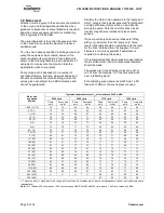
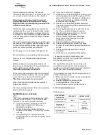
Set the alarm at (t+tb-ta+5)

C [(t+tb-ta+10)

F]

and the trip at 100

C (212

F) for oil lubrication

and 105

C (220

F) for grease lubrication

It is important, particularly with grease lubrication, to
keep a check on bearing temperatures. After start up
the temperature rise should be gradual, reaching a
maximum after approximately 1.5 to 2 hours. This
temperature rise should then remain constant or
marginally reduce with time.

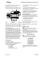
5.5.5 Normal vibration levels, alarm and trip

For guidance, pumps generally fall under a
classification for rigid support machines within the
International rotating machinery standards and the
recommended maximum levels below are based on
those standards.

Alarm and trip values for installed

pumps should be based on the actual
measurements (N) taken on site on the bearing
housings of the pump in the fully commissioned as
new condition.

The example (N) value is given for the preferred
operating flow region (typically this may extend to 70
to 120 % of the pump best efficiency point); outside
the preferred flow region the actual vibration
experienced may be multiplied by up to 2.

These standard values can vary with the rotational
speed and the power absorbed by the pump. For
any special case, do not hesitate to consult us.

Measuring vibration at regular intervals will then
show any deterioration in pump or system operating
conditions.

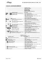
Vibration Velocity -

unfiltered

Horizontal Configuration

mm/s (in./s) r.m.s.

Normal

N

5.6 (0.22)

Alarm

N

x 1.25

7.1 (0.28)

Shutdown Trip

N

x 2.0

11.2 (0.44)

5.5.6 Stop/start frequency

Pump sets are normally suitable for the number of
equally spaced stop/starts per hour shown in the table
below. Check actual capability of the driver and
control/starting system before commissioning.

Motor rating kW (hp)

Maximum start ups per

hour

Up to 15 (20)

15

Between 15 (20) and 90 (120)

10

90 (120) to 150 (200)

6

Above 150 (200)

Refer

Where duty and standby pumps are installed it is
recommended that they are run alternately every
week.

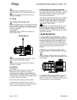
5.6 Stopping and shutdown

According to hydraulic conditions of

the installation and its automation degree, stop and
restart procedures can have different forms.
Nevertheless all of them must respect imperatively
the following rules:

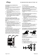
5.6.1 Stopping < 1 hour

a) Isolate motor.
b)

Avoid reverse rotation of the pump.

c)

Make sure that the discharge line pressure does
not reach the foot valve.

5.6.2 Stopping < 1 month

a) Isolate motor.
b)

Avoid reverse rotation of the pump.

c)

Make sure that the discharge line pressure does
not reach the foot valve.

d)

Close the outlet valve. Eventually close the inlet
valve.

e) Switch off external power supply,

flushing/quench, cooling liquid.

5.6.3 Shutdown > 1 month

a) Isolate motor.
b)

Avoid reverse rotation of the pump.

c)

Make sure that the discharge line pressure does
not reach the foot valve.

d)

Close the outlet valve. Eventually close the inlet
valve.

e) Switch off external power supply,

flushing/quench, cooling liquid.

f)

Keep the pump fully filled with water. In case of
pumped liquid other than water, drain the pump
entirely.

g)

Turn once per week the pump shaft of one or
two turns.

h)

Never restart the pump without carrying out the
verifications recommended before starting (see
§ 5.4.1).

When ambient temperatures are

likely to drop below freezing point, the pump and any
cooling and flushing arrangements must be drained
or otherwise protected.

5.6.4 Restarting in continuous running

a) Ensure that the pump is completely full of liquid.
b)

Ensure a continuous supply with a sufficient
available NPSH.

c)

Ensure a backpressure so that the motor power
is not in excess.

d)

Respect the starting frequency

imposed by the motor manufacturer.

e)

Protect the pump against water hammer

when stopping or starting.

Содержание 71576526

Страница 1: ... stage centrifugal close coupled pump with an axial suction and a vertical axis discharge PCN 71576526 03 07 E Installation Operation Maintenance These instructions must be read prior to installing operating using and maintaining this equipment ...

Страница 2: ... Piping 15 4 4 Electrical connections 17 4 5 Protection systems 18 5 COMMISSIONING START UP OPERATION AND SHUTDOWN 18 5 1 Direction of rotation 18 5 2 Guarding 18 5 3 Priming and auxiliary supplies 18 5 4 Starting the pump 19 5 5 Running the pump 19 5 6 Stopping and shutdown 21 5 7 Hydraulic mechanical and electrical duty 22 5 8 Pumps for Food Use or Potable Water 22 Page 6 MAINTENANCE 22 6 1 Gene...

Страница 3: ...l duty 5 7 22 Inspection 6 2 2 and 6 2 3 24 Installation 4 15 Internal coating 6 2 6 25 Lifting 2 3 11 Location 4 1 15 Maintenance 6 22 Maintenance schedule 6 2 23 Mechanical seal 6 2 4 24 Nomenclature 3 2 12 Nameplate 1 7 1 8 Operating limits see 3 1 12 Ordering spare parts 6 3 1 25 Parts lists 8 2 29 Piping 4 3 15 Protection systems 4 5 18 Pump masses 2 2 2 10 Receipt and unpacking 2 1 10 Recomm...

Страница 4: ...e applicable this document incorporates information relevant to these Directives and Approvals To confirm the Approvals applying and if the product is CE marked check the serial number plate markings and the Certification See section 9 Certification 1 3 Disclaimer Information in these User Instructions is believed to be reliable In spite of all the efforts of Flowserve Corporation to provide sound...

Страница 5: ...s and health and safety personnel and follow all plant safety requirements and applicable safety and health laws and regulations 1 6 3 Safety action This is a summary of conditions and actions to prevent injury to personnel and damage to the environment and to equipment For products used in potentially explosive atmospheres section 1 6 4 also applies NEVER DO MAINTENANCE WORK WHEN THE UNIT IS CONN...

Страница 6: ...ability and cavitation vibration 1 6 4 Products used in potentially explosive atmospheres The following instructions for pumps and pump units when installed in potentially explosive atmospheres must be followed to help ensure explosion protection The terminology and procedures ensure that the installed pump is in compliance with the European Directive 94 9 EC known as the ATEX Directive which is m...

Страница 7: ...when the liquid temperature varies and the pump could be installed in different hazardous atmospheres In this case the user is responsible for ensuring that the pump surface temperature does not exceed that permitted in the particular hazardous atmosphere If an explosive atmosphere exists during the installation do not attempt to check the direction of rotation by starting the pump unfilled Even a...

Страница 8: ... ancillary systems Where there is the potential hazard of a loss of a seal barrier fluid or external flush the fluid must be monitored If leakage of liquid to atmosphere can result in a hazard the installation of a liquid detection device is recommended 1 6 4 7 Maintenance to avoid the hazard CORRECT MAINTENANCE IS REQUIRED TO AVOID POTENTIAL HAZARDS WHICH GIVE A RISK OF EXPLOSION The responsibili...

Страница 9: ...lowserve or a noise specialist if assistance is required in combining the values It is recommended that where exposure approaches the prescribed limit then site noise measurements should be made The values are in sound pressure level LpA at 1 m 3 3 ft from the machine for free field conditions over a reflecting plane For estimating sound power level LWA re 1 pW then add 17 dBA to the sound pressur...

Страница 10: ...ctions concerning handling Boxes crates pallets or cartons may be unloaded using fork lift vehicles or slings dependent on their size and construction See 2 3 1 for positioning of slings To lift heavy pieces above 25 kg 55 lb use a winch adapted to the mass and in accordance with the current local regulations To lift machines or pieces with one or several suspension rings only use hooks and chains...

Страница 11: ...parts the relevant materials and parts should be recycled or disposed of using an environmentally acceptable method and local regulations If the product contains substances which are harmful to the environment these should be removed and disposed of in accordance with current regulations This also includes the liquids and or gases in the seal system or other utilities Make sure that hazardous subs...

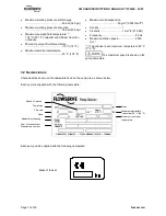
Страница 12: ...lbm ft3 Density 1 Viscosity 1 mm2 s 31 SSU Frequency 50 Hz Maximum rotation speed 2850 min 1 1 If mechanical seal maximum temperature 80 C 176 F The maximum speed is shown on the pump nameplate 3 2 Nomenclature Characteristics shown on the nameplate fixed on the pump are as shown below Each pump is supplied with the following nameplate Each pump unit is supplied with the following nameplate Mass o...

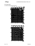
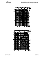
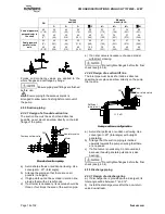
Страница 13: ...FM USER INSTRUCTIONS ENGLISH 71576526 03 07 Page 13 of 32 flowserve com 3 3 Coverage charts 3 3 1 2850 min 1 50 Hz Operating ranges Q H ...

Страница 14: ...FM USER INSTRUCTIONS ENGLISH 71576526 03 07 Page 14 of 32 flowserve com ...

Страница 15: ... frame level or on the discharge flange with a levelling instrument b Admissible defect 0 5 mm for 1 meter 0 02 in for 3 3 ft c Wedge under the pump Level Frame level 4 3 Piping The user must verify that the equipment is isolated from any external sources of vibration Protective covers are fitted to the pipe connections to prevent foreign bodies entering during transportation and installation Ensu...

Страница 16: ...t 20 total angle b Arrange the piping so that there are no air pockets no bulges c If high points cannot be avoided in suction line provide them with air relief cocks d If a strainer is necessary its net area should be three or four times the area of the suction pipe e If an inlet valve is necessary choose a model with direct crossing Do not tighten flanges before the final check see 4 3 4 4 3 2 2...

Страница 17: ...installing equipment on site Attention must be paid to ensure that the techniques used during wiring installation do not increase electromagnetic emissions or decrease the electromagnetic immunity of the equipment wiring or any connected devices If in doubt contact Flowserve for advice Before connecting the electric power supply if the device has been kept in a damp atmosphere have the insulation ...

Страница 18: ...rotation exists the customer must install a reverse rotation protection device The customer must install all equipment required to avoid water hammer 5 COMMISSIONING START UP OPERATION AND SHUTDOWN These operations must only be carried out by qualified personnel 5 1 Direction of rotation Starting or operating pumps with the wrong direction of rotation can be harmful to the pumps Ensure that the pu...

Страница 19: ...g d Check the direction of rotation of the motor Refer to the rotation arrow of the pump e DO NOT FORGET TO REMOUNT THE SHIELD GRID ON THE MOTOR STOOL f Open all inlet valves if existing g Close the outlet valve and the bypass valve h Ensure inlet pipe and pump casing are completely full of liquid 5 4 2 First pump start up Suction valves must be fully open when pump is running Never run the pump d...

Страница 20: ... as this operation is completed 5 5 3 Pump fitted with a mechanical seal A mechanical seal ensures a seal without leakage and does not need any adjustment Nevertheless if a light leakage occurs during start up it should disappear after the initial running in of the friction faces 4213 4200 2445 4240 4610 With a mechanical seal the maximum temperature is limited to 80 C 176 F whatever the internal ...

Страница 21: ...tem before commissioning Motor rating kW hp Maximum start ups per hour Up to 15 20 15 Between 15 20 and 90 120 10 90 120 to 150 200 6 Above 150 200 Refer Where duty and standby pumps are installed it is recommended that they are run alternately every week 5 6 Stopping and shutdown According to hydraulic conditions of the installation and its automation degree stop and restart procedures can have d...

Страница 22: ...degradation It is important that NPSHA NPSHR The margin between NPSHA NPSHR should be as large as possible If any change in NPSHA is proposed ensure these margins are not significantly eroded Refer to the pump performance curve to determine exact requirements particularly if flow has changed If in doubt please consult your nearest Flowserve office for advice and details of the minimum allowable ma...

Страница 23: ...eration b Any auxiliary systems installed must be monitored if necessary to ensure they function correctly c During cleaning of the pump ensure the compatibility between the cleaning products and the gaskets d Verify the condition of the gaskets e Gland packing must be adjusted correctly to give visible leakage and concentric alignment of the gland follower to prevent excessive temperature of the ...

Страница 24: ...top the pump as soon as possible Have an approved seal vendor replace or repair the seal 4213 4200 2445 4240 4610 6 2 5 Gland packing 6 2 5 1 Pump fitted with a packed gland A well run in and correctly adjusted packing gland requires little maintenance If after some time the leakage becomes too great the gland should be tightened again in order to return these to a normal level If re tightening is...

Страница 25: ...ering spares the following information should be quoted 1 Pump serial number 2 Pump size 3 Part name 4 Part number 5 Number of parts required The pump size and serial number are shown on the pump nameplate To ensure continued satisfactory operation replacement parts to the original design specification should be obtained from Flowserve Any change to the original design specification modification o...

Страница 26: ...e Dismantle inlet and outlet pipeworks as well as all pipeworks f REMOVE PUMP TAKING INTO ACCOUNT SAFETY 1 AND HANDLING 2 2 PROCEDURES ANY DISASSEMBLY REPAIR OR REASSEMBLY WILL BE CARRIED OUT UNDER FLOWSERVE RESPONSABILITY EITHER DIRECTLY BY THE AFTER SALES SERVICE OR BY OTHER FLOWSERVE AGENTS WHO WILL GET THE REQUIRED INSTRUCTIONS AND APPROVALS THIS IS THE CASE OF AUTHORIZED REPAIRERS WHOSE ADDRE...

Страница 27: ...k the suction and discharge pipes valves back pressure Worn wear ring surfaces Foresee pump mending CONSULT FLOWSERVE Seizure jamming CONSULT FLOWSERVE Excessive strains on flanges Check the flange connections and eliminate strains pipe positioning or elastic sleeves mounting Defective mechanical seal Check and replace all the mechanical seal parts Mechanical seal CONSULT FLOWSERVE Defective motor...

Страница 28: ...FM USER INSTRUCTIONS ENGLISH 71576526 03 07 Page 28 of 32 flowserve com 8 PARTS LIST AND DRAWINGS 8 1 Sectional drawing ...

Страница 29: ...e instructions where applicable Examples are certificates for CE marking ATEX marking etc If required copies of other certificates sent separately to the Purchaser should be obtained from the Purchaser for retention with these User Instructions 10 OTHER RELEVANT DOCUMENTATION AND MANUALS 10 1 Supplementary User Instructions manuals Supplementary instructions such as for a driver instrumentation co...

Страница 30: ...FM USER INSTRUCTIONS ENGLISH 71576526 03 07 Page 30 of 32 flowserve com Nota ...

Страница 31: ...FM USER INSTRUCTIONS ENGLISH 71576526 03 07 Page 31 of 32 flowserve com Nota ...

Страница 32: ... Pacific Flowserve Pte Ltd 200 Pandan Loop 06 03 04 Pantech 21 Singapore 128388 Telephone 65 6775 3003 Fax 65 6779 4607 Local Flowserve factory representatives North America Flowserve Pump Division 5599 E Holmes Road Memphis TN 38118 USA Telephone 1 800 343 7867 Fax 1 901 259 3946 South America Flowserve do Brasil Ltda Av Don Helder Camara 5451 20771 001 Rio de Janerio Brasil Telephone 55 21 599 4...

Отзывы: