


MN301520 Rev A1
15
|
Application Examples
Step
Seven
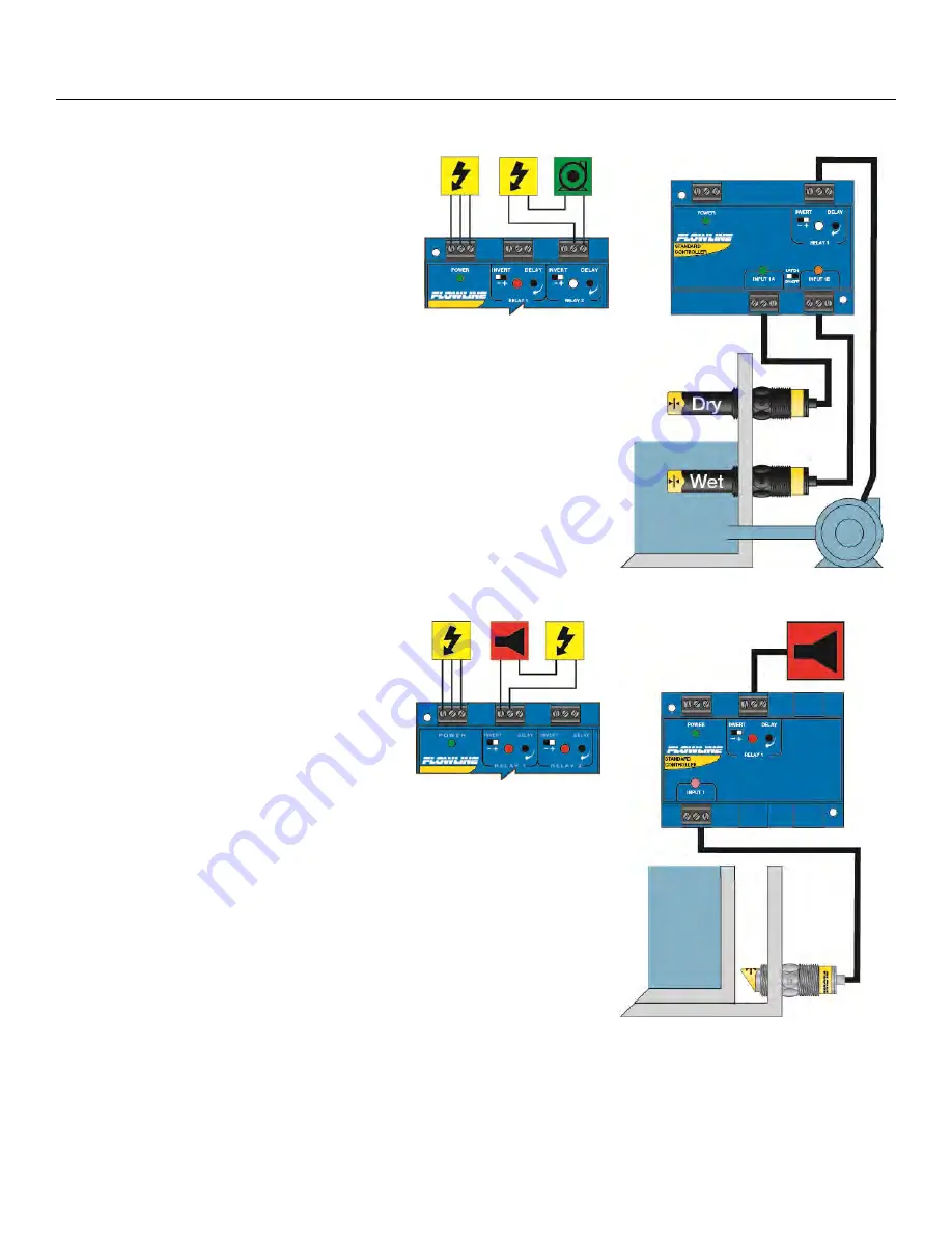
AUTOMATIC EMPTY:
Similar system logic can be used for an
automatic empty operation. In this example,
we will use a pump to empty a tank. The
system still consists of a tank with a high level
sensor, a low level sensor, and a pump that is
controlled by the controller.
Note:
Fail-safe design is critical in an
application where the tank is passively filled.
A power failure to the controller or the pump circuits may cause the tank
to overflow. A redundant high alarm is critical to prevent an overflow.
Connect the pump to the NO side of the relay. In this case, Invert
should be OFF, when the relay is energized, the pump will run and
empty the tank. The relay indicator will correspond directly to the on/off
status of the pump.
Note:
If the pump motor load exceeds the rating of the controller’s
relay, a stepper relay of higher capacity must be used as part of the
system design.
LEAK DETECTION:
A leak detection switch is installed either
inside the interstitial space of the tank or
through the outer wall. The switch will
remain wet 99.99% of the time. Only when
liquid comes into contact with the switch will
the relay close to activate an alarm.
The alarm is connected to the NC side of the
relay to allow for a power failure alarm.
Note:
The sensor is normally dry. In this condition, we want the relay
to be energized so the alarm does not sound: i.e., the Red relay LED
should be on whenever the Input LED is Amber. So we turn Invert On.
If liquid comes into contact with the switch, the switch activates, the
relay de-energizes, and the alarm sounds.