background image

205288 D/E


12 

E


20.0 Optional tapping unit – digital tapping depth display  


„tapping“  

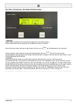
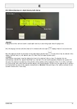
Engage the machine with main switch. adjust depth end stop to max drilling depth. Select tapping mode. 


Move the tapping tool down with star wheel on the material surface and push 

 display shows zero as actual value. 


Move the tapping tool with the star wheel on requested tapping depth. Press 

 Values shown now are identical in the 

display of actual value (l.h.) and desired value (r.h.) Start motor and adjust spindle speed. 

à


tapping 

Using the star wheel again, move the tapping tool down to the material in the core hole. The tapping tool cuts 
automatically until either the adjusted depth has been reached or the end switch signalizing that pinion is operated. At 
this point, the electronic reverses the turning direction of the spindle and the tapping tool turns l.h. out of the cut thread. 
The return spring of the pinion pulls the spindle upwarts in the starting position. At this point, the upper limiter is operated 
and the electronic reverses in the originally turning direction. 

Attention

: After switching on, the machine will start in both 

operation modes with a 5 sec delay! 

Spindle speed 

Actual value  

 Desired value  

Содержание P30 ST

Страница 1: ...g machine as described on the front page meets all general health and safety rules CEE regulations Applicable harmonized standards CEE machine standards 2006 42 EG DIN EN ISO 12100 1 and 2 CEE EMV 89 336 EWG EN 60204 part1 The low voltage regulation is applied Remscheid den 10 05 2010 Dipl Wirtsch Ing J P Arnz Entwicklungsleitung No Technische Unterlagen sowie Datendokumentation sind bei Arnz FLOT...

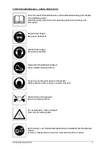
Страница 2: ...Keep eyes protected Gehörschutz tragen Keep ears protected Geeignete Arbeitskleidung tragen Wear suitable working clothes Tragen sie bei langen Haaren ein Haarnetz Wear protective hair covering to contain long hair Werkstücke sicher spannen Secure workpieces firmly Vor umlaufenden Teilen schützen Take care of rotating parts Bei Wartungs und Instandhaltungsarbeiten grundsätzlich den Netzstecker zie...

Страница 3: ...4000 min Digital Digital 420 kg kg kg max 150 mm 70 kg max 390 mm a c b a SB TB TBZ b c kW 400V P35 ST 30 35 mm max M24 MK3 125 mm 280 mm 110 mm 420x340 mm 1 5 2 0 kW 1 R1 125 2000 min 1 R2 80 1280 min Digital Digital 275 kg kg kg P30 ST 25 30 mm max M20 MK3 125 mm 260 mm 110 mm 420x340 mm 0 9 1 45 kW 1 125 4000 min Digital Digital 275 kg kg kg Stufe 1 125 2000 1 min Stufe 2 250 4000 1 min ...

Страница 4: ...Tischverstellung Option 9 0 Bedienung Alle Maschinen werden am Hauptschalter ein bzw ausgeschaltet Hierzu muß der Not Aus Schlagtaster entriegelt sein Der elektrisch verriegelte Bohrschutz muß hierbei geschlossen Schutzposition sein Falls vorhanden kann nun mittels Pol Wendeschalter die Drehzahlstufe gewählt und von Drehzahlstufe 1 rechts drehend in Drehzahlstufe 1 linksdrehend z B zum Gewindeschn...

Страница 5: ...nd wieder klemmen Achtung Quetschgefahr Tisch gegen Herabfallen sichern 15 2 Bei Maschinen mit Zahnstangenverstellung zum Verstellen des Tisches bzw Kopfes die Tisch bzw Kopf klemmung lösen und mittels Handkurbel verstellen 15 3 Achtung Quetschgefahr bei motorischer Verstellung des Tisches Klemmung lösen Nach Positionierung Tisch wieder klemmen 16 0 Regulierung der Rückzugfederspannung Achtung Net...

Страница 6: ...en Parameter wird der Gewindebohrer mittels Bohrkreuz bis zum Anschneiden in die Kernlochbohrung nach unten geführt Der Gewindebohrer zieht sich nun selbsttätig soweit in die Kernlochbohrung hinein bis die eingestellte Gewindetiefe erreicht wird oder der Endschalter Pinole Unten betätigt wird An dieser Stelle schaltet die Elektronik die Drehrichtung der Spindel um und der Gewindebohrer dreht sich ...

Страница 7: ...ine switch on off the main switch Hereto first unlock the emergency push button optional The electrical drill guard must be closed safe position If present use the polarity reverse switch to select the right speed level now you can change from spindle speed step 1 right hand into spindle speed step 1 left hand e g for tapping The switch drilling tapping option selects the direction of the spindle ...

Страница 8: ...nst falling 15 2 On machines with a rack untension the clamping lever adjust the table height by means of the hand crank and tension the clamping lever 15 3 Attention Squeezing danger before adjusting the drilling table untighten the clamping lever After positioning retighten again 16 0 Adjustment of the return spring tension Attention Disconnect the machine from the electrical supply 16 1 Remove ...

Страница 9: ...d à tapping Using the star wheel again move the tapping tool down to the material in the core hole The tapping tool cuts automatically until either the adjusted depth has been reached or the end switch signalizing that pinion is operated At this point the electronic reverses the turning direction of the spindle and the tapping tool turns l h out of the cut thread The return spring of the pinion pu...

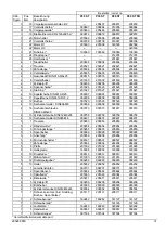
Страница 10: ...208029 2 5 Not Aus Schlagtaster 208022 208022 208022 208022 2 6 Schalter Kühlmittel Option 009461 009461 009461 009461 2 7 Schalter Beleuchtung Option 009461 009461 009461 009461 2 8 Schalter Motorische Maschinen höhenverstellung Option 008687 008687 2 9 Schalter Motorische Tischverstellung Option 008687 008687 3 1 Spindel 205350 205350 205481 205481 3 2 Pinole 205346 205346 205357 205357 3 3 Rill...

Страница 11: ...658 4 14 Sechskantschraube DIN933 M8x90 007973 007973 007973 007973 4 15 Zylinderschraube DIN912 M8x85 009758 009758 009758 009758 4 16 Sechskantmutter DIN985 M8 006401 006401 006401 006401 5 1 Traverse 205853 205853 205853 205853 5 2 Rändelmutter 205854 205854 205854 205854 5 3 Führungsstange 205855 205855 205855 205855 5 4 Spannhebel 009099 009099 009099 009099 5 5 Anschlag 205856 205856 205856 ...

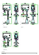
Страница 12: ...205288 D E 15 1 2 3 4 5 6 7 8 9 10 1 2 3 4 5 6 7 8 9 10 1 2 3 4 5 6 7 8 9 Abb fig 1 P30 P35 ST P40 ST P30 P35 ST ...

Страница 13: ...205288 D E 16 1 7 8 9 2 3 4 5 6 Abb fig 2 ...

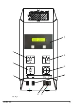
Страница 14: ...205288 D E 17 Abb fig 3 1 1 2 2 3 3 4 23 24 25 A A A A A A A A B 12 12 6 6 7 8 9 10 13 14 15 16 17 18 19 20 21 22 5 5 11 11 ...

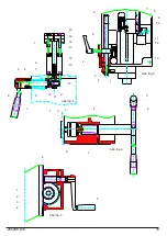
Страница 15: ...205288 D E 18 Abb fig 5 Abb fig 6 Abb fig 7 6 7 4 5 10 10 11 12 13 2 1 3 8 8 12 12 13 13 14 15 16 11 9 9 Abb fig 4 6 7 4 5 2 1 3 8 4 5 6 7 2 1 3 5 6 2 3 4 1 ...

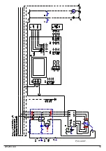
Страница 16: ...P30 40 ST 205288 D E 19 ...

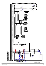
Страница 17: ...205288 D E 20 P30 40 STFB ...

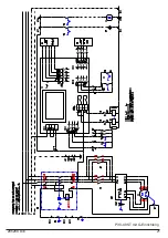
Страница 18: ...205288 D E 21 P30 40 ST mit G Einrichtung ...

Страница 19: ...ing instruction Betriebsstunden service hours 40 200 1 Säule column 2 Pinole pinion shaft 3 Laufhülse running bush 4 Tischverstellung adjustment of table CL68 DIN 51502 CL68 GRAFLOSCON A G 1Ultra 4 3 2 1 K2K 20 205288 D E ...

Отзывы: