


12
MAINTENANCE /
REP
AIR
TROUBLESHOOTING
SAFETY
/
SPECIFICA
TIONS
GETTING ST
ARTED
OPERA
TION
ASSEMBL
Y /
INST
ALLA
TION
INSTALLATION (CONTINUED)
a. Strip insulation ¾ in. (19 mm).
b. With wire ends even, insert wires into the connector and tighten until
secure.
c. Insert the connector all the way into the tube until the connector rests
on the bottom of the tube.
NOTE: If having difficulty getting the twist-on connector down into the tube
when using small gauge wires, use a thin, non-conductive object to push
the connector to the bottom of the tube. Upon removal of the object, ensure
that no voids or water paths remain in the grease.
d. Fold the wires into the channels.
e. Close the cap.
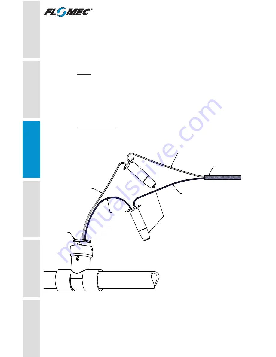
Wiring Diagram
This diagram shows connection to a RAINBIRD
®
Flow Smart Module.
Connections to other flow controllers may vary.
12
12
RED
BLACK
DBR/Y-6
SPLICE KIT
FLOW INSERT
TO FLOW " + "
ON FLOW SMART
MODULE
TO FLOW " - "
ON FLOW SMART
MODULE
18 AWG CABLE
to CONTROLLER
Figure 9