background image


INSTALLATION 

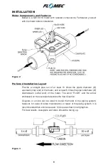
Meter Components and Features 

Below  is  a  QS100-10  meter  with  labeled  components.  Familiarize  yourself 
with the meter before installation. 


Figure 2 


Preferred Installation Layout 

Provide  a  straight  pipe  run  of  at  least  10  times  the  pipe's  diameter  (Ø) 
upstream (inlet end) of the meter, and at least 5 times the pipe's diameter (Ø) 
downstream  (outlet  end)  of  the  meter.  The  word  “FLOW”  and  the  arrow 
embossed on the coverplate denotes the flow direction. 

Couplers  or  unions  can  be  used  to  install  the  meter  in  the  piping  system; 
however, for ease of future maintenance or repair of the piping system, it is 
recommended that unions be used. Unions are shown in all graphics. 
For best results, coverplate and wires should be facing up. 


Figure 3 


Содержание QS100-10

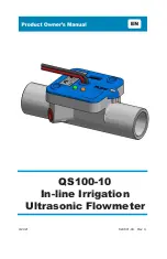
Страница 1: ...QS100 10 In line Irrigation Ultrasonic Flowmeter 3 2021 920901 03 Rev C ...

Страница 2: ...o back cover for information regarding this product s warranty and other important information DO NOT RETURN THIS PRODUCT TO THE STORE Please contact Great Plains Industries Inc before returning any product If you are missing parts or experience problems with your installation contact our Customer Support Department We will be happy to assist you Call 888 996 3837 or 316 686 7361 Email meters gpla...

Страница 3: ...3 TABLE OF CONTENTS Getting Started 4 General Safety Instructions 5 Electrical Mechanical Specifications 6 Installation 8 Operation 12 Troubleshooting 13 Service Warranty 15 ...

Страница 4: ...re cutters tape measure PVC pipe fittings as needed PVC pipe primer PVC pipe cement Direct burial wire splices valve box 18 AWG wire cable Direct Burial Controller manufacturer may recommend thicker gauge wire for longer distances UNPACKING Contents QS100 10 In line Irrigation Ultrasonic Flowmeter Owner s Manual Inspect After unpacking the unit inspect carefully for any damage that may have occurr...

Страница 5: ...id and or environment should be considered prior to putting into service Product should never be operated outside its published specifications for temperature or pressure See specifications for your model Make sure flow and pressure have been eliminated from process pipe prior to installing or removing product Installation near high electromagnetic fields and high current fields is not recommended...

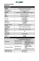
Страница 6: ...ng Pressure 150 PSI 70 F 10 3 bar 21 1 C Process Fluid Temp Range 32 F to 140 F 0 C to 60 C Storage Temperature 40 F to 140 F 40 C to 60 C Field Calibration No Inlet Outlet Connections 1 in Male Spigot Weight 0 42 lbs 0 19kg ELECTRICAL Powered by DC power provided by customer controller 7 5V dc min to 36V dc max OFF State Current 200µA typical OFF State V High Supply Voltage OFF State Current Supp...

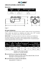
Страница 7: ...ration fluid condition adjoining pipe schedule and entrapped air Customers should always validate accuracy and adjust K factor as needed using the K factor adjustment menu of your controller Pipe Schedule Typical K Factor Controller Hydrawise K Factor Litre Pulse Rain Master K Factor Offset Reference Pulses Gal Pulses Litre Sch 40 0 4211 0 0266 115 0 142 5 37 6 Sch 80 0 3963 0 0250 108 0 151 4 40 ...

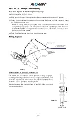
Страница 8: ...eam inlet end of the meter and at least 5 times the pipe s diameter Ø downstream outlet end of the meter The word FLOW and the arrow embossed on the coverplate denotes the flow direction Couplers or unions can be used to install the meter in the piping system however for ease of future maintenance or repair of the piping system it is recommended that unions be used Unions are shown in all graphics...

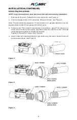
Страница 9: ...ence in 5 and 6 below is for general reference Use the sequence best suited for your piping and overall layout 3 Following the PVC cement manufacturer s instructions apply PVC cement to a meter end and fitting and quickly assemble while the cement is fluid Hold the cemented parts together for at least 30 seconds Repeat for other end of meter See Figure 6 4 Attach meter with attached fittings to pi...

Страница 10: ...lled immediately below the meter and valve box Figure 7 Wiring Connections Below ground wiring connections require a waterproof splicing method to wire the meter wires to the wire cable from the controller The following splice sequence Figure 8 shows a 3M DBR Y 6 splice kit used with 18 AWG wire cable from the controller See next page for splice instructions and wiring diagram Figure 8a Figure 8b ...

Страница 11: ...s use a thin non conductive object to push the connector to the bottom of the tube Upon removal of the object ensure that no voids or water paths remain in the grease 8d Fold the wires into the channels 8e Close the cap Wiring Diagram Figure 9 Optional Above Ground Installation The meter can be installed above ground as long as proper plumbing and wiring outlined in previous pages are followed and...

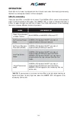
Страница 12: ...s are OFF No Flow Low Power Mode GREEN LED flashes ON OFF at a rate of approximately 2 blinks per second No Flow or Reverse Flow Active Mode GREEN LED flashes ON OFF at a rate of approximately 8 blinks per second Low Flow Active Mode GREEN LED flashes ON OFF at a rate of approximately 8 blinks per second and the AMBER LED flashes ON OFF at a rate that is proportional to the rate of water flow thru...

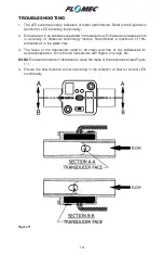
Страница 13: ...y of ultrasonic technology meters Recommend a maximum of 10 entrained air in the water flow 3 The faces of the transducers need to be clean and free of oily substances for accurate operation Do not touch transducers with fingers oily rags etc DO NOT use wire brushes or abrasives to clean the faces of the transducers see Figure 11 4 Ensure the flow direction arrow is pointing in the direction of fl...

Страница 14: ..._________________ ___________________________________________ ___________________________________________ ___________________________________________ ___________________________________________ ___________________________________________ ___________________________________________ ___________________________________________ ___________________________________________ ______________________________...

Страница 15: ...sales receipt This warranty shall not apply if A The product has been altered or modified outside the warrantor s duly appointed representative B The product has been subjected to neglect misuse abuse or damage or has been installed or operated other than in accordance with the manufacturer s operating instructions To make a claim against this warranty or for technical assistance or repair contact...

Страница 16: ...antability or fitness for any particular purpose other than for which it was designed This warranty gives you specific rights and you may also have other rights which vary from U S state to U S state Note In compliance with MAGNUSON MOSS CONSUMER WARRANTY ACT Part 702 governs the resale availability of the warranty terms IP68 2021 Great Plains Industries Inc All Rights Reserved Great Plains Indust...

Отзывы: