FLIR
LEPTON® Engineering Datasheet
The information contained herein does not contain technology as defined by the EAR, 15 CFR 772, is publicly available,
and therefore, not subject to EAR. NSR (6/14/2018).
Information on this page is subject to change without notice.
Lepton Engineering Datasheet, Document Number: 500-0659-00-09 Rev: 203
46
The MOSI (Master Out/Slave In) signal is not currently employed and should be grounded or set low.
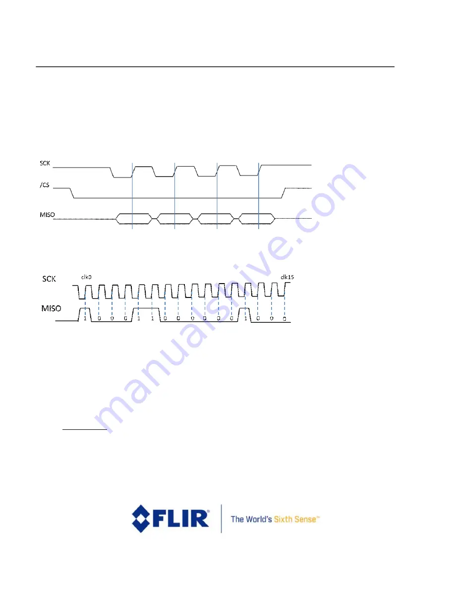
Implementations are restricted to a single master and single slave. The Lepton uses SPI Mode 3 (CPOL=1,
CPHA=1); SCK is HIGH when idle. Data is set up by the Lepton on the falling edge of SCK and should be sampled by
the host controller on the rising edge. See
. Data is transferred most-significant byte first and in big-
endian order.
provides an example of the transmission of the value 0x8C08.
Figure 18 - SPI Mode 3 (CPOL=1, CPHA=1)
Figure 19 - SPI Bit Order (transmission of 0x8C08)
The maximum clock rate is 20 MHz. The minimum clock rate is a function of the number of bits of data per frame
that need to be retrieved. As described in the sections that follow, the number of bits of data varies depending
upon user settings (video format mode, telemetry mode). As an example, in Raw14 mode and telemetry disabled,
there are 60 video packets per frame for an 80x60 array, each 1312 bits long, at approximately 26 frames per
second. Therefore, the minimum rate is on the order of 2 MHz.
4.2.2
VoSPI Protocol
–
Lepton 1.5, 1.6, 2.0 and 2.5
VoSPI is built on a collection of object types as defined hierarchically below.
•
VoSPI Packet
:
The Lepton VoSPI protocol is based on a single standardized VoSPI packet, the minimum
“transaction” between master and slave. Each video packet contains data for a single video line or
telemetry line. In addition to video packets, the VoSPI protocol includes discard packets that are provided
when no video packets are available.


