


FLIR
MR176
‐
GETTING
STARTED
Document
Identifier:
MR176
‐
QS
‐
mul_AA
MR176
‐
GETTING
STARTED
‐
EN
USER
GUIDE
LOCATION:
Please
read
the
detailed
User
Guide,
located
in
the
MR176
internal
memory,
for
complete
details
on
all
MR176
features
and
functions.
Connect
the
meter
to
a
PC
using
the
supplied
USB
cable
and
open
the
folder
entitled
‘DOC’
to
access
the
User
Guide.
The
User
Guide
is
also
available
on
the
website
www.flir.com.
Register
for
Extended
Warranty
and
Product
Updates
at
www.flir.com/testwarranty
Quick
Steps
Charge
the
battery
by
connecting
the
supplied
USB
cable
to
a
PC
before
first
use.
Press
to
power
ON
(press
and
hold
to
power
OFF).
The
MR176
first
powers
up
in
the
IGM
Custom
mode.
Use
the
Main
Menu
to
change
modes
(press
Select
for
the
Main
Menu).
View
IR
Thermal
Image,
Moisture,
Air
Temperature,
Relative
Humidity
(RH
%),
Dew
Point,
and
Mixing
Ratio
on
the
display.
Press
the
Laser
button
to
activate
the
laser
and
display
crosshairs.
Place
the
internal
pinless
moisture
sensor
against
a
test
surface
(apply
light
pressure)
to
take
relative
moisture
measurements.
Press
the
image
capture
button
to
freeze
the
view
and
store
a
screen
‐
shot.
Press
image
capture
again
to
confirm,
or
back
to
cancel.
Use
Image
Review
mode
(from
Main
Menu)
to
view/delete
stored
images.
Transfer
images
to
PC
using
supplied
USB
cable.
Refer
to
the
informative
User
Guide
for
detailed
instructions
on
External
Probe
use,
Material
Groups,
Relative
(Set
Reference)
mode,
High
Alarm,
Psychrometrics,
and
more.
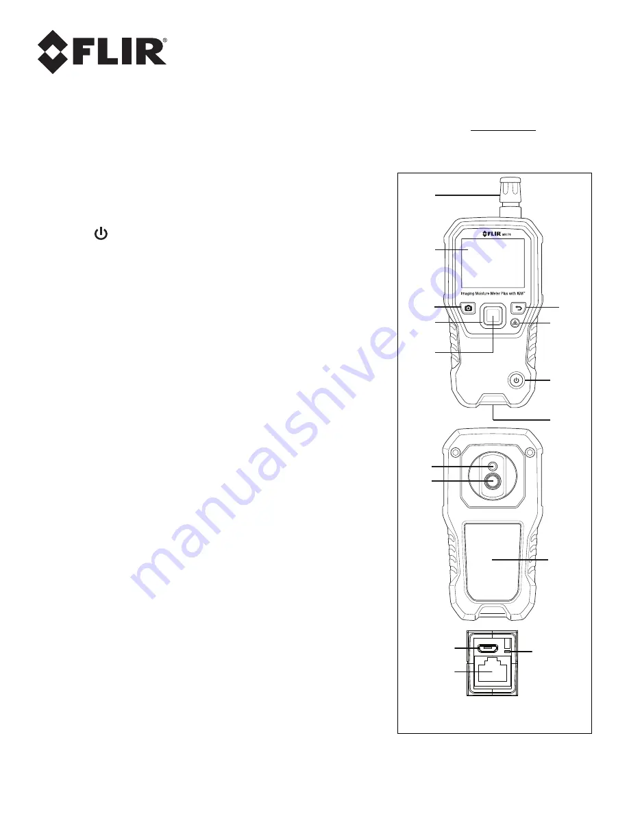
For
Fig.
1
at
right,
see
the
descriptions
below:
1.
Temperature
and
Relative
Humidity
Sensor
(MR01)
2.
Color
Graphical
Display
3.
Screen
Capture
button:
Press
to
hold/record/store
IR
images
4.
Navigation
buttons
(ring)
for
up/down
‐
left/right
scrolling
5.
Select
button
(center):
Press
for
Main
Menu
6.
Back
button:
Press
to
return
from
a
menu
screen
7.
Laser
Pointer
and
Crosshairs
button
8.
Power
button:
Short
press
ON,
long
press
OFF.
9.
USB,
External
Probe
jack,
and
Battery
charging
LED
10.
Laser
pointer
lens
(back)
11.
Thermal
imaging
lens
(back)
12.
Internal
Pinless
Moisture
sensor
(back)
13.
Micro
USB
Port
(bottom)
14.
External
Probe
Jack
(bottom)
15.
Battery
Charging
LED
status
lamp
(bottom)
1
2
3
4
5
6
7
8
9
10
11
12
13
14
15
Fig.
1
Description


