


Installation
9
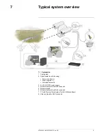
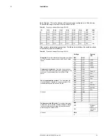
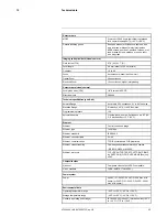
Figure 9.2
FLIR G300 pt series camera exclusion zone. Height 480 mm (18.9″), diameter 740 mm
(29.1″).
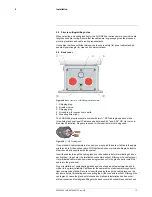
9.4
Camera mounting
FLIR G300 pt series cameras must be mounted upright on top of the mounting surface,
with the base below the camera. The unit should not be hung upside down.
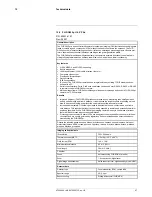
The FLIR G300 pt series camera can be secured to the mount with four 5/16″ or M8
bolts, as shown below.
Note
Use washers to protect the painting.
Once the mounting location has been selected, verify that both sides of the mounting
surface are accessible.
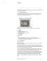
Figure 9.3
FLIR G300 pt series camera mounting (mm)
Connect and operate the camera as a bench test at ground level prior to mounting the
camera in its final location.
Use a thread-locking compound such as Loctite 242 or an equivalent with all metal-to-
metal threaded connections.
Using the template supplied with the camera as a guide, mark the location of the holes
for mounting the camera. If the template is printed, ensure that it is printed to scale so
that the dimensions are correct.
Once the holes are drilled in the mounting surface, install four (4) 5/16″ or M8 bolts
through the base of the camera.
#T559900; r. AB/35735/35735; en-US
12
Содержание G300 pt Series
Страница 1: ...User s manual FLIR G300 pt ...
Страница 2: ......
Страница 3: ...User s manual FLIR G300 pt T559900 r AB 35735 35735 en US iii ...
Страница 4: ......
Страница 42: ...Mechanical drawings 13 T559900 r AB 35735 35735 en US 36 ...
Страница 44: ...CE Declaration of conformity 14 T559900 r AB 35735 35735 en US 38 ...
Страница 45: ......
Страница 79: ......