FT-112(D) Panel Weighing Indicator, Technical Manual, Rev.1.0.0, May 2019
Page
20
of
170
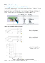
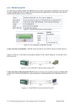
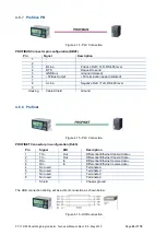
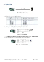
4.6.2 Digital Load Cell Connection (Only FT-112D)
The digital load cell wiring should be made carefully before energizing to avoid FT-112D and load cells from
damages. The instrument cable between the instrument and junction box must be shielded and convenient for
high speed RS485 interfacing. The wire diameter of the instrument cable should be selected for maximum 0.5
volt drop between the instrument and junction box.
Pin No.
Definition Description
1
A
+ RS485 for DLC
interfacing
2
B
- RS485 for DLC
interfacing
3
- V
Ground
4
NC
Not connected
5
NC
Not connected
6
+V
LC
Power output for DLCs
7
-
Not used
Shield
Protective Earth
Table 4.2
– Pin configuration of the digital load cell terminal of FT-112D.
Figure 4.4
– The FT-112D connection with junction box
Figure 4.5
– Installation with junction box
Figure 4.6
– Daisy-chain installation
1
7
DLC #1
DLC #2
DLC #n
to power supply
PE
Instrument
Cable
FT-112D
Cabinet
Platform
DLC #1
DLC #2
DLC #n
to power supply
PE
Instrument
Cable
FT-112D
J.BOX
Cabinet
Platform


