background image


Rev: 
 

    A


Revision Date: 

04/22/21013 


Page 8 of 15


    MAN 

– FD171DMT ver HDSDI-CAN 


Power/Video 

 
Pin out for P1 (5W1 Combo-D Female Receptacle) 
 

Supplied 


Connector   


P/N: Conec – 3005W1SM99A10X 


Coax Contact  


P/N: Conec – 132J30029X (for use with RG179)* 


*Other cable type contacts available from Conec 


    MATING FACE 


Pin 

Number 

Description 

28VDC Power 

28VDC Ground 

Can low 

Can high 

A1 

HDSDI IN 


All manuals and user guides at all-guides.com

Содержание FD171DMT

Страница 1: ...lation and Operation Manual 17 1 LCD and Display Mount Manufactured by MILIC LLC with marketing support from Flight Display Systems This product does not have FAA PMA approval TECHNICAL SUPPORT 1 678 867 6717 or www FlightDisplay com All manuals and user guides at all guides com a l l g u i d e s c o m ...

Страница 2: ... Systems 1765 Grassland Parkway Alpharetta GA 30004 1 678 867 6717 Phone 1 678 867 6742 Fax sales FlightDisplay com www FlightDisplay com For the most current copy of all product manuals please visit our website at www FlightDisplay com For more product support information please visit the following link at http support FlightDisplay com All manuals and user guides at all guides com ...

Страница 3: ...ing 7 Power Video 8 1 Pinout 5W1 Combo D 8 Technical Drawing 9 Technical Drawing 10 Operation Instructions 11 1 Button Controls 11 2 Remote Control Buttons 12 Troubleshooting 13 1 Video Noise 13 2 Snow or Sweeping Lines 13 3 No Power to Monitor or No Video Input 13 4 Color Distortion 13 5 Remote Control Inoperable 13 Technical Support 14 Instructions for Continued Airworthiness 14 Warranty 15 Log ...

Страница 4: ...hat allow installation in the smallest of mounting areas with the minimum of interface equipment Built with retrofit aircraft integration in mind this display has a single HDSDI CAN Video input Front View Side View FD171DMT R Shown In the Deployed State Press Here to Deploy Monitor Press Here to Stow Monitor NEVER PRESS HERE All manuals and user guides at all guides com ...

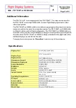
Страница 5: ...otion up and right into the aisle while the FD171DMT ver HDSDI CAN R is installed on the Right side of the bulkhead deploys up and left into the aisle To deploy the monitor press the Press Here button on top of the enclosure Specifications Display Size 11 89 W x 8 91 H Display Type 17 1 Color LCD Display Color 16 7 Million Colors Dimensions Stowed 14 25 W x 23 150 H x 2 00 D Dimensions Deployed 32...

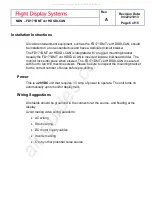
Страница 6: ...en stowed The FD171DMT ver HDSDI CAN is secured with four to ten 10 machine screws Please be sure to inspect the mounting bracket for the correct number of holes before pre drilling Power This is a 28VDC unit that requires 1 3 Amp of power to operate The unit turns on automatically upon monitor deployment Wiring Suggestions All shields should be grounded to the connector at the source and floating...

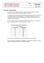
Страница 7: ...8 VDC power system and a total of 50 feet of wire between the circuit breaker monitor and ground Example 22awg wire has 16 2 Ohms per 1000 feet this equates to 81 Ohms for 50 feet 1 3 Amp of current on 81 Ohms will drop 1 06 Volts Resistance of Wire Type M22759 16 Gauge Gauge AWG OHMS 1000 24 26 20 22 16 20 20 9 88 16 4 81 12 2 02 10 1 26 8 701 Also use short heavy gauge wire and a clean tight con...

Страница 8: ...o D Female Receptacle Supplied Connector P N Conec 3005W1SM99A10X Coax Contact P N Conec 132J30029X for use with RG179 Other cable type contacts available from Conec MATING FACE Pin Number Description 1 28VDC Power 2 28VDC Ground 3 Can low 4 Can high A1 HDSDI IN All manuals and user guides at all guides com ...

Страница 9: ...Rev A Revision Date 04 22 21013 Page 9 of 15 MAN FD171DMT ver HDSDI CAN Technical Drawing All manuals and user guides at all guides com ...

Страница 10: ...Rev A Revision Date 04 22 21013 Page 10 of 15 MAN FD171DMT ver HDSDI CAN Technical Drawing All manuals and user guides at all guides com ...

Страница 11: ...will turn on and look for a valid input on the last known source If no input is found the display will go to standby mode Pressing the Select button will select new video input Button Controls Located at the top center of the are 8 buttons Their functions are shown below BUTTON DESCRIPTION POWER Toggles the power ON or OFF Also wakes the display up from SLEEP mode MENU Opens the MENU AUTO Auto adj...

Страница 12: ...Rev A Revision Date 04 22 21013 Page 12 of 15 MAN FD171DMT ver HDSDI CAN Remote Control Multi Unit Remote button functionality may vary All manuals and user guides at all guides com ...

Страница 13: ...so cause noise Stand off the wires if necessary If snow or sweeping lines persist it is possible that the ground is at an incorrect point in the aircraft Try moving the ground to another location No power to Monitor or No video Input Verify correct wiring Check the base receptacle connectors for possibly damaged pins Check that the video source is 1 Powered on 2 In Play mode and 3 Displaying video...

Страница 14: ...Flight Display Systems 1765 Grassland Parkway Alpharetta GA 30004 Phone 1 678 867 6717 Fax 1 678 867 6742 Email sales FlightDisplay com For further product information technical data and sample wiring diagrams please click on the Dealers section of our web site at www FlightDisplay com Instructions for Continued Airworthiness The FD171DMT ver HDSDI CAN is designed not to require regular general ma...

Страница 15: ...ceipt of the failed hardware remanufacture or replace the unit at our discretion Flight Display Systems will pay Ground Shipping charges for warranted items Charges for express shipment will be the responsibility of the sender This warranty is not transferable Any implied warranties expire at the expiration date of this warranty We shall not be liable for incidental or consequential damages This w...

Отзывы: