


Rev:
G
Revision Date:
10/31/2014
Page 10 of 18
MAN
– FD141CV
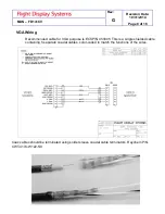
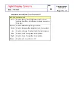
Power/Video
Pin out for P1 (High Density DB-15 Receptacle)
Connector
P/N: M24308/2-286 or Equivalent
Crimp Contacts
P/N: M39029/57-354 or Equivalent
Pin
Number
Description
1
28VDC Power
2
28VDC Ground
3
Composite Video - Signal
4
Composite Video - Shield
5
S-Video Y - Signal
6
S-Video Y - Shield
7
S-Video C - Signal
8
S-Video C - Shield
9
Red Video (Pin 1 on Standard VGA)
10
Green Video (Pin 2 on Standard VGA)
11
Blue Video (Pin 3 on Standard VGA)
12
RGB Ground (Pins 6,7,8 on Standard
VGA)
13
Sync Ground (Pin 10 on Standard VGA)
14
Horizontal Sync (Pin 13 on Standard
VGA)
15
Vertical Sync (Pin 14 on Standard VGA)


