


Printed in Canada
TAC1000 Manual
June 19, 2013
Page 5
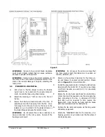
Figure 5
WARNING:
Failure to have correct blade clearance
could result in blade contact that can cause extensive
damage to people and equipment.
WARNING:
Failure to have the correct clearance for
the rotary union could result in premature failure of the
rotary union and/or damage to objects contacting the
rotary union.
3.0
PNEUMATIC LINE INSTALL
A.
Drill a hole in the fan shroud to allow the flexible
nylon hose to be routed into the engine compart-
ment. Secure the hose using hose clamps.
B.
Attach the incoming ¼” O.D. air line to the front of
he fan.
C.
Ensure that the hose clears all parts of the fan. If
possible, secure the hose away from the fan. Com-
mon ways to do this are to zip tie the hose to the
radiator core, or to attach it to the radiator frame or
the bolted flanges between the radiator cores.
WARNING:
Do not secure the air line so tight as to
cause a side load on the rotary union. Failure of the
bearings could result.
WARNING:
Do not secure the air line so loose that
the hose could contact the blades due to sudden air
reversal, vibration, etc...
D.
Ensure you have proper clearance for the rotary un-
ion and blades to nearest contact point(s). Please
refer to
Figure 5
for more information.
E.
Install the pneumatic control. Follow the instructions
included with the control kit. If you did not purchase
a kit from Flexxaire, see section 3.2 for pneumatic
specifications.
F.
Rotate the fan by hand and check for obstructions.
A final check will be required once the air supply has
been connected to the fan. A minimum of 90 PSI
(620 kPa) will be required to fully reverse the
blade pitch. Spin the fan by hand with the blade
pitch reversed and check for obstructions.
G.
Tighten the fan belts and replace all the fan guards
and safety equipment.
H.
Attach the “WARNING” label to the machine, on a
housing, guard, or any location near the fan where it
can be easily seen.


