
5. START-UP AND OPERATION
Guidelines for System Connection
The connection should be executed in a way which does not induce
stresses.
It is recommended to install vent valves at the highest point of the
system.
The system should be executed so that, in the case of a failure, it is
possible to disassemble the device. For this purpose it is best to use
shut-off valves just by the device.
The system with the heating medium must be protected against an
increase of the heating medium pressure above the permissible value
(1.6 MPa).
While screwing exchanger to pipeline - connecting stubs has to be hold
by wrench.
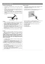
Start Up
Before connecting the power supply check the correctness of connection
of the fan motor and the controllers. These connections should be
executed in accordance with their technical documentation.
Before connecting the power supply check whether the mains voltage is
in accordance with the voltage on the device data plate.
Before starting the device check the correctness of connection of the
heating medium conduits and the tightness of the system.
The electrical system supplying the fan motor should be additionally
protected with a circuit breaker against the effects of a possible short-
circuit in the system.
Starting the device without connecting the ground conductor is forbidden.
Operation
The device is designed for operation inside buildings, at temperatures
above 0
o
C. In low temperatures (below 0ºC) there is a danger of freezing
of the medium.
The manufacturer bears no responsibility for damage of the heat
exchanger resulting from freezing of the medium in the exchanger. If
operation of the device is expected at temperatures lower than 0º, then
glycol solution should be used as the heating medium, or special
automatic systems should be used for protecting against freezing of the
medium in the exchanger.
It is forbidden to place any objects on the heater or to hang any objects
on the connecting stubs.
The device must be inspected periodically. In the case of incorrect
operation of the device it should be switched off immediately.
It is forbidden to use a damaged device. The manufacturer bears no
responsibility for damage resulting from the use of a damaged device.
If it is necessary to clean the exchanger, be careful not to damage the
aluminium lamellas.
For the time of performing inspection or cleaning the device, the electrical
power supply should be disconnected.
In case water is drained from the device for a longer period of time, the
exchanger tubes should be emptied with compressed air.
It is not allowed to make any modification in the unit. Any modification
causes in warranty loss.
Periodic inspections
To keep proper technical parameters Flowair recommends periodic
service (every 6 months) of fan heaters on behalf of the user.
During inspections user should:
Check heat exchanger, if is it filled with dirt or dust. If necessary - use
pressurized air stream to clean the exchanger’s lamellas,
Check heat exchanger, if is it filled with dirt or dust. If necessary - use
pressurized air stream to clean the exchanger’s lamellas,
Check fan blades, in case of dirt use damp cloth and remove dirt,
Check bracket installation,
Check heat exchanger and hydraulic connection correctness,
Check wires insulation,
Check power supply,
Check medium flow,
Check levelling of the unit.
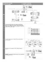
Содержание LEO L1
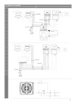
Страница 8: ... 9 SRQ3d 4 CONNECTION DIAGRAMS ...


