


Installation, Operation, & Maintainance Guide
Style 60/62/65
PREPARATION
•
Verify that equipment has been properly
shut off and rendered inoperative according
to plant safety protocol (e.g. lockout/tagout
procedures).
1
. Disassemble the pump seal chamber, in
accordance with the pump OEM instructions, to
expose the existing seal.
Document how the seal chamber is
disassembled for re-assembly.
2
. Carefully remove the existing seal rotary and
stationary assemblies, taking care not to
damage the shaft or seat counterbore.
3
. Clean the shaft, shaft sleeve (if present), seal
chamber face, and seat counterbore surfaces
of rust, burrs, grit, sharp edges, and set screw
damage using fine emery cloth. Wipe clean.
Avoid making flat spots, reducing shaft
diameter, or increasing seat bore diameter.
4
. If the pump is equipped with a shaft sleeve,
verify the condition of its O-ring or gasket and
ensure that it is properly located (fully engaged
against step/hook/snap ring).
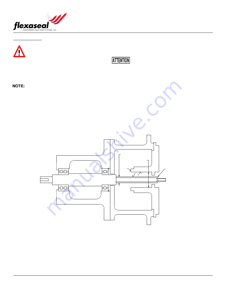
5
. Sealing surfaces and the shaft or shaft sleeve
must have at least a 63 Ra-
µ
in surface finish as
seen in
6
. For ease of installation, the leading edge of the
shaft or sleeve should be chamfered as shown
in
and all parts should be deburred.
(B) BORE ID
(A) SLEEVE OD
.030 MIN. x 30°
63
63
63
Figure 1: Surface finish and chamfer locations. Fully assembled pump without seal.
Page 2 of 9