background image

Lit. No. 43573/43583/43593, Rev. 01 

15 

August 15, 2013

Spreader Harness

Control

65 1/4”

47

42

19 1/2” 

5”

Load
View

Negative

Auger Motor 

Spinner 

Positive

Vibrator Negative 

Auger Negative 

Spinner Negative 

Spinner Positive 

Auger Positive

Vibrator Positive 

Male

Female

Vibrator Plug

Black

Red

Load
View

Auger 
Red Positive (+)

Auger
Black Negative (-)

Spinner
Black Negative (-)

Vibrator
Black Negative (-)

Spinner
Red Positive (+)

Vibrator
Red Positive (+)

Red
Positive (+)

Black
Negative (-)

HARNESS DIAGRAM

Содержание POLY-CASTER

Страница 1: ...for FISHER POLY CASTER LT hopper spreaders with serial numbers 0000 and higher CAUTION Read this manual before installing or operating the spreader A DIVISION OF FISHER LLC Fisher Engineering August 15 2013 Lit No 43583 Rev 01 78902 50 Gordon Drive Rockland Maine 04841 2139 www fisherplows com ...

Страница 2: ......

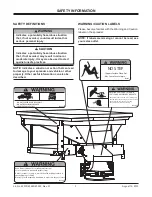
Страница 3: ...actices WARNING Indicates a potentially hazardous situation that if not avoided could result in death or serious personal injury ROTATING PARTS AND FLYING OB JECTS CAN CAUSE INJURY OR DEATH Keep hands arms feet and loose clothing away Shut off power ans stop engine before servicing Read owners manual before operating Keep bystanders at least 60 ft away D6544 NO STEP Slippery Surface When Wet May C...

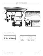
Страница 4: ... REMOVE SPREADER WITH MATERIAL IN HOPPER FASTEN SPREADER DOWN WITH APPROVED RATCHET STRAPS AND BOLT KIT REAR FRAME LOCATOR BARS MUST BE IN PLACE BEFORE OPERATING VEHICLE DANGER D6547 ROTATING AUGER CAN CAUSE SERIOUS INJURY OR DEATH Keep arms hands and loose clothing away from auger Shut off control and unplug spreader before servicing D6335 SERIAL NO 0 5 cu yd MODEL NO MMYYLL PPPPP SAFETY INFORMAT...

Страница 5: ...ompliant Backup Alarm This alarm is required for OSHA governed employers CAUTION Disconnect electric and or hydraulic power and tag out if required before servicing or performing maintenance CAUTION DO NOT leave unused material in hopper Material can freeze or solidify causing unit to not work properly Empty and clean after each use NOTE Lubricate grease fittings after each use Use a good quality ...

Страница 6: ...ETY CAUTION Batteries normally produce explosive gases which can cause personal injury Therefore do not allow flames sparks or lit tobacco to come near the battery When charging or working near a battery always cover your face and protect your eyes and also provide ventilation Batteries contain sulfuric acid which burns skin eyes and clothing Disconnect the battery before removing or replacing any...

Страница 7: ...xceed GVWR or GAWR as found on the driver side cornerpost of vehicle WARNING New untitled vehicle installation of a spreader requires National Highway Traffic Safety Administration altered vehicle certification labeling Installer to verify that struck load of snow or ice control material does not exceed GVWR or GAWR rating label and complies with FMVSS CAUTION Read and adhere to manufacturer s ice...

Страница 8: ...ht into the payload to determine the maximum volume of material that can be carried WARNING Overloading could result in an accident or damage Do not exceed GVWR or GAWR ratings as found on the driver side door cornerpost of the vehicle See Loading Section to determine maximum volumes of spreading material 7 Compare the maximum volume to determine the maximum height of the material in the hopper sp...

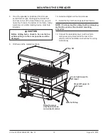
Страница 9: ...er back approximately 1 to allow proper clearance 7 Install stop bars using supplied hole patterns see illustration below To achieve the best position you may need to drill additional holes in the bracket in order to properly position the spreader If there are interferences relocate the holes making sure there are at least two forward and two rearward of the front to back centerline CAUTION Before...

Страница 10: ... tighten all four cap screws 11 Install the four ratchet straps as shown below NOTE It is important for safety that this strapping method be used as the standard mounting procedure 12 Connect the spreader power cord to vehicle main power plug mounted at the rear of the vehicle refer to installation instructions for wiring instructions Cross left upper to right lower Strap from rear of vehicle to f...

Страница 11: ...e harness or a control module Generally either side of the steering wheel is a good location to place the hole 5 Connect power leads to the battery Red POSITIVE Black NEGATIVE Always connect to the primary battery if using a dual battery system Secure loose loom to any other large or medium vehicle harness with medium duty cable ties to secure wiring harness NOTE If adding an inline fuse use a 60 ...

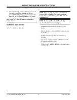
Страница 12: ...Read lead labels before attaching to power source or ground No other devices may be spliced into wiring harness Any repairs to wiring harness must be done with heat shrink butt connectors If inline fuse is installed use a 60 amp maxi fuse or circuit breaker 3 Push the ON OFF switch on the control to check for power After power has been confirmed push the ON OFF switch again to turn OFF The electri...

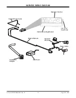
Страница 13: ...43583 43593 Rev 01 13 August 15 2013 HARNESS WIRING DIAGRAM 1 4 x 1 2 Cap Screw Control Power Cable Spreader Control Control Mounting Bracket Vehicle Harness Connector Adapter Dust Cover Power Cable Spreader Harness ...

Страница 14: ...uger Mold Cap Blue 12 GA Vibrator Orange 10 GA Vibrator Spinner 10 GA White Auger 10 GA Red Vibrator 12 GA Orange Spinner 10 GA Black Hot Circuit Grd Circuit Auger 10 GA Green Vibrator 12 GA Blue Vehicle Harness Control Power Cable 3 8 Terminal w Heat Shrink Black Red 124 Tubing Front View Red to Positive Black to Negative HARNESS DIAGRAM ...

Страница 15: ...nner Positive Vibrator Negative Auger Negative Spinner Negative Spinner Positive Auger Positive Vibrator Positive Male Female Vibrator Plug Black Red Load View Auger Red Positive Auger Black Negative Spinner Black Negative Vibrator Black Negative Spinner Red Positive Vibrator Red Positive Red Positive Black Negative HARNESS DIAGRAM ...

Страница 16: ...Lit No 43573 43583 43593 Rev 01 16 August 15 2013 Spinner Main Input Auger and Vibrator not supplied on drawing ELECTRICAL ROUTING ...

Страница 17: ...FINAL CHECKLIST Verify dielectric grease is applied to all electrical connections Verify wire harnesses and battery cables are properly secured away from hot or moving parts Verify vehicle battery cable has sufficient ground clearance when spreader is removed from truck ...

Страница 18: ...turer may require or recommend optional equipment for spreaders Do not exceed vehicle ratings with a spreader Fisher Engineering offers a limited warranty for all spreaders and accessories See separately printed page for this important information The following are registered or unregistered trademarks of Douglas Dynamics LLC FISHER POLY CASTER LT Printed in U S A Fisher Engineering 50 Gordon Driv...

Отзывы: